Welding device

A welding device and connecting technology, which is applied to the parts of the connecting device, the coupling device, the device for connecting/disconnecting the connecting parts, etc. Disengagement or looseness, preventing plugging looseness, and improving the service life

Inactive Publication Date: 2017-06-13
童浩
View PDF5 Cites 7 Cited by
  • Summary
  • Abstract
  • Description
  • Claims
  • Application Information

AI Technical Summary

Problems solved by technology

[0002] At present, electric welding machines are used more and more widely, and they rely on plugging and connecting to electricity to work normally. Therefore, whether the electric welding machine is plugged in firmly is the basis for determining whether the electric welding machine can work normally. The setting is long and the weight is heavy, the pick-and-place process is extremely difficult and easily affected by external factors such as dragging and pulling, which makes the plug connection loose and leads to poor contact. And it is exposed to the outside world when it is not plugged in. In the case of people accidentally stepping on or plugging in too much force, it will be bent and damaged, making it impossible to use it normally and shortening the service life. Have requests

Method used


Image

  • Welding device
  • Welding device
  • Welding device

Examples


Embodiment Construction

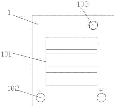
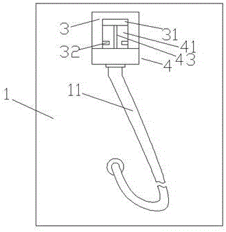
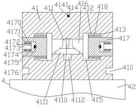
[0023] Such as Figure 1-Figure 7 As shown, a welding device of the present invention includes a connecting piece 51 installed in the socket 5, an electric welding machine 1, an adapter 3 fixed on the rear side of the electric welding machine 1, and an In the connecting part 4 inside, a heat exhaust window 101 is provided in the middle of the front end of the electric welding machine 1, and a positive and negative output port 102 is provided on the front end of the electric welding machine 1 below the heat exhaust window 101. The front end of the electric welding machine 1 on the upper right of the heat window 101 is provided with an adjustment hinge 103, and the connecting part 4 includes a connecting head 41 and a pinching member 42 fixed on the bottom of the connecting head 41. A groove 414 is arranged in the top end surface of the head 41, and a trigger 4141 is arranged in the groove 414. A first sliding cavity 411 is arranged in the coupling head 41 below the groove 414. ...


PUM


Abstract

The invention discloses a welding device, which comprises a connecting piece installed in a socket, an electric welding machine, a connecting piece fixed on the rear side of the electric welding machine, and a connecting part installed in the connecting piece, and the middle part of the front end of the electric welding machine There is a heat exhaust window, the front end of the electric welder below the heat exhaust window is provided with positive and negative output ports, the front end of the electric welder on the upper right of the heat exhaust window is provided with an adjustment hub, and the joint part includes a joint head and a joint fixed on the joint. The pinching piece at the bottom of the head is provided with a groove in the end surface of the top of the connecting head, a trigger is arranged in the groove, a first sliding chamber is arranged in the connecting head below the groove, and the left and right sides of the first sliding chamber are correspondingly provided. There is a second sliding chamber, the second sliding chamber deviates from the side of the first sliding chamber and is provided with a first groove, the second sliding chamber is provided with a first push block, and the inner side of the first push block is provided with a The outer side of the first push block is provided with a lock block that passes through the first groove and the outer wall of the joint head, and a stud is provided in the first sliding cavity, and the bottom of the stud is connected to the motor; the structure of the present invention is simple, Easy to use, automatic control locking, easy to plug in and high stability after plugging in, prevent accidental touch and cause loose plugging, and improve the service life at the same time.

Description

technical field [0001] The invention relates to the technical field of welding, in particular to a welding device. Background technique [0002] At present, electric welding machines are used more and more widely, and they rely on plugging and connecting to electricity to work normally. Therefore, whether the electric welding machine is plugged in firmly is the basis for determining whether the electric welding machine can work normally. The setting is long and the weight is heavy, the pick-and-place process is extremely difficult and easily affected by external factors such as dragging and pulling, which makes the plug connection loose and leads to poor contact. And it is exposed to the outside world when it is not plugged in. In the case of people accidentally stepping on or plugging in too much force, it will be bent and damaged, making it impossible to use it normally and shortening the service life. Have requests. Contents of the invention [0003] The technical pro...

Claims


Application Information

Patent Timeline
Patent Type & Authority Applications(China)
IPC IPC(8): H01R13/62H01R13/629H01R13/639H01R13/66
CPCH01R13/6205H01R13/629H01R13/639H01R13/66
Inventor 童浩
Owner 童浩
Why Eureka
Try Eureka