
Five-end high-voltage direct-current power transmission system

A high-voltage direct current (HVDC) and power transmission system technology, applied in power transmission and AC networks, etc., can solve the problems of single structure of multi-terminal direct current power transmission system, and achieve the effect of improving power supply reliability, reducing power consumption cost, and flexible structure.

Pending Publication Date: 2017-06-13
安徽康力节能电器科技有限公司
View PDF6 Cites 3 Cited by
  • Summary
  • Abstract
  • Description
  • Claims
  • Application Information

AI Technical Summary

Problems solved by technology

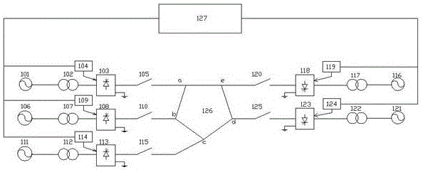
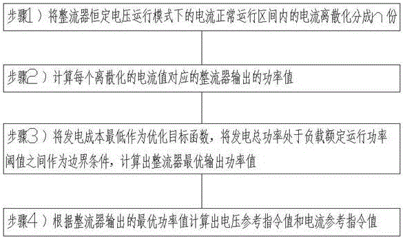
[0002] Due to the imbalance of energy and economic development, the large capacity of high-voltage DC transmission and the advantages of long-distance transmission have played an important role in my country's "West-to-East Power Transmission, National Networking" strategy, but the traditional 2-terminal DC can only achieve point-to-point With the development of the economy and the construction of the power grid, it is necessary to require the power grid to be able to supply power from multiple sources and receive power from multiple locations. Therefore, the multi-terminal DC transmission system (MTDC) developed on the 2-terminal DC transmission system is more In order to be flexible and quick, however, the existing multi-terminal DC transmission system structure is relatively simple, mainly based on the structure of the four-terminal HVDC transmission system. Therefore, the present invention proposes a more flexible five-terminal DC transmission system, and through multiple The voltage joint control between converter stations will minimize the fault current when a ground fault occurs, and at the same time control the output power value of each power source according to the power generation cost and load power demand value of each power source in the multi-terminal HVDC transmission system, so as to Improve power supply reliability and reduce electricity costs

Method used


Image

  • Five-end high-voltage direct-current power transmission system
  • Five-end high-voltage direct-current power transmission system

Examples


Embodiment Construction

[0012] figure 1 It is the block diagram of the five-terminal HVDC transmission system: figure 1 The five-terminal high-voltage direct current transmission system mainly includes: AC input power supply 101, AC input power supply 106, AC input power supply 111, transformer 102, transformer 107, transformer 112, rectifier 103, rectifier 108, rectifier 113, controller 104, controller 109 , controller 114, circuit breaker 105, circuit breaker 110, circuit breaker 115, a pentagonal DC transmission line with five nodes a, b, c, d, e, circuit breaker 120, inverter 118, controller 119 , transformer 117, AC power load 116, circuit breaker 125, inverter 123, transformer 122, AC power load 121 and main controller 127, characterized in that: AC input power supply 101 is connected to transformer 102, transformer 102 is connected to rectifier 103 , the two ends of the circuit breaker 105 are respectively connected to the rectifier 103 and node a of the pentagonal DC transmission line, the t...


PUM


Abstract

The invention discloses a five-end high-voltage direct-current power transmission system. The system comprises five convertor stations, a transformer, a circuit breaker and a pentagonal direct-current grid. Fault current is reduced to the minimum when a ground fault happens through combined control of voltage between the convertor stations, and meanwhile, according to the power generation cost and load power required values of all power sources of a multi-end high-voltage direct-current power transmission system, the output power value of each power source is controlled, so that the power distribution reliability is improved and the power consumption cost is reduced.

Description

technical field [0001] The invention relates to a five-terminal high-voltage direct current transmission system, in particular to the control of a multi-terminal high-voltage direct current transmission system. Background technique [0002] Due to the imbalance of energy and economic development, the large capacity of high-voltage DC transmission and the advantages of long-distance transmission have played an important role in my country's "West-East Power Transmission, National Networking" strategy, but the traditional 2-terminal DC can only achieve point-to-point With the development of the economy and the construction of the power grid, it is inevitable that the power grid can realize multi-power supply and multi-drop power receiving. Therefore, the multi-terminal DC transmission system (MTDC) developed on the 2-terminal DC transmission system is more In order to be flexible and fast, however, the existing multi-terminal DC transmission system structure is relatively simple...

Claims


Application Information

Patent Timeline
Patent Type & Authority Applications(China)
IPC IPC(8): H02J3/36
CPCH02J3/36Y02E60/60
Inventor 李国红
Owner 安徽康力节能电器科技有限公司
Learn More