Method of driving vibration actuator with enhanced sliding efficiency, vibration drive device, and mechanical apparatus

A vibration actuator and vibration drive technology, used in the field of mechanical equipment and driving vibration actuators, can solve the problems of small degrees of freedom in mechanical design of vibration actuators, and achieve the goal of improving sliding efficiency, reducing restrictions, and improving durability. Effect

Active Publication Date: 2017-06-13
CANON KK
View PDF10 Cites 2 Cited by
  • Summary
  • Abstract
  • Description
  • Claims
  • Application Information

AI Technical Summary

Problems solved by technology

[0004] However, it is difficult to say that sufficient sliding efficiency can be obtained by the technique described in Japanese Patent Laid-Open No. 2007-202227, and therefore, further improvement is required
In addition, the n-order vibration and the 3n-order vibration used in the technique described in Japanese Patent Laid-Open No. 2007-202227 have a large difference between the respective natural frequencies of the vibration, which leads to the problem that the vibration-induced Significant limitations (small degrees of freedom) exist in the mechanical design (structural design) of the actuator

Method used


Image

  • Method of driving vibration actuator with enhanced sliding efficiency, vibration drive device, and mechanical apparatus
  • Method of driving vibration actuator with enhanced sliding efficiency, vibration drive device, and mechanical apparatus
  • Method of driving vibration actuator with enhanced sliding efficiency, vibration drive device, and mechanical apparatus

Examples


Embodiment Construction

[0038] The present invention will now be described in detail with reference to the accompanying drawings showing embodiments of the invention.

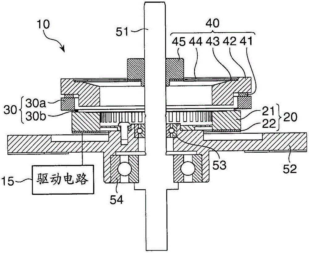
[0039] figure 1is a schematic longitudinal sectional view of the vibration driving device according to the first embodiment of the present invention. The vibration drive device includes a vibration actuator 10 and a drive circuit 15 for driving the vibration actuator 10 . The vibration actuator 10 includes a vibrating element 20, a driven element 30, and a pressing mechanism 40, each of which is formed in a ring shape. In addition, the vibration actuator 10 includes a shaft 51 , a housing 52 , and bearings 53 and 54 .

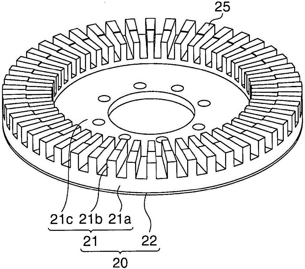
[0040] The vibration element 20 includes a piezoelectric element 22 which is an electromechanical energy conversion element and an elastic body 21 joined to the elastic body 21 . The pressing mechanism 40 includes a vibration-isolating rubber 41 , a pressure spring receiving part 42 , a pressure spring receiving rub...


PUM


Abstract

A method of driving a vibration actuator. The vibration actuator includes a vibration element including a piezoelectric element as an electromechanical energy conversion element and an elastic body which is joined to the piezoelectric element, and a driven element which is brought into pressure contact with the elastic body. Driving vibration is excited in the vibration element by applying a drive signal to the piezoelectric element, whereby the vibration element and the driven element are moved relative to each other. The driving vibration is vibration in which at least n-th-order vibration and 2n-th-order vibration are combined, n being a natural number.

Description

technical field [0001] The present invention relates to a method for driving a vibration actuator, a vibration driving device and a mechanical device equipped with the vibration driving device, and more particularly, to a method for increasing the sliding efficiency of a vibration actuator so as to improve the durability of the vibration actuator sex technology. Background technique [0002] The vibration actuator has such a feature that enables the vibration actuator to generate a large low-speed torque and maintain its state by friction after driving, wherein the vibration actuator makes the vibration element and the driven element press-contact each other and Vibration of the vibrating element is excited, thereby causing the vibrating element and the driven element to move relative to each other. By focusing on such features, for example, in image pickup apparatuses such as single-lens reflex cameras, vibration actuators have been put into practical use as lens drive mot...

Claims


Application Information

Patent Timeline
Patent Type & Authority Applications(China)
IPC IPC(8): H02N2/00
CPCH02N2/001H02N2/006H04N23/673H02N2/106H02N2/14H02N2/163G02B7/08G02B21/26G02B27/646H02N2/0015H04N23/55H04N23/663H04N23/67H04N23/687G02B7/14H02N2/008H02N2/12
Inventor 土屋聪司森敬夫
Owner CANON KK
Why Eureka
Try Eureka