A terminal device and its depth-of-field control method

A technology of terminal equipment and control method, applied in the direction of TV, color TV parts, TV system parts, etc., can solve the problems of slow system running speed and high cost, reduce load, reduce CPU cost and software complexity degree, the effect of increasing the speed of the depth of field operation and the effect

Active Publication Date: 2019-07-16
深圳酷赛通信科技有限公司
View PDF5 Cites 0 Cited by
  • Summary
  • Abstract
  • Description
  • Claims
  • Application Information

AI Technical Summary

Problems solved by technology

[0004] In view of the shortcomings of the above-mentioned prior art, the purpose of the present invention is to provide a terminal device and its depth-of-field control method to solve the problem of high cost and low system operating speed caused by the existing terminal device adopting a CPU supporting dual ISP channels to achieve the depth-of-field effect. slower problem

Method used


Image

  • A terminal device and its depth-of-field control method
  • A terminal device and its depth-of-field control method
  • A terminal device and its depth-of-field control method

Examples


Embodiment Construction

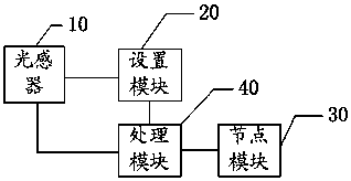
[0027] The present invention provides a terminal device and a depth-of-field control method thereof. By using a light sensor instead of a newly added camera for object occlusion detection, the CPU cost of the terminal device is reduced, and the operating speed and effect of the depth-of-field are improved. In order to make the object, technical solution and effect of the present invention more clear and definite, the present invention will be further described in detail below with reference to the accompanying drawings and examples. It should be understood that the specific embodiments described here are only used to explain the present invention, not to limit the present invention.

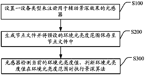
[0028] see figure 1 , the method for controlling the depth of field of a terminal device provided by the present invention includes:

[0029] S100. Set a device type to register a light sensor for assisting the depth of field effect;

[0030] S200. Generate a node file and save the preset ambie...


PUM


Abstract

The present invention discloses a terminal device and its depth-of-field control method. The depth-of-field control method includes: A. setting a device type to register a light sensor for assisting the depth-of-field effect; B. generating a node file and setting the preset environment The brightness range is saved to the node file; C. The light sensor detects the current ambient brightness value, and executes the depth-of-field algorithm when judging that the ambient brightness value is within the ambient brightness range. The present invention uses a light sensor to replace the camera added in the prior art to perform object occlusion detection, without using a CPU supporting dual ISP channels, thereby reducing the CPU cost and software complexity of the terminal device, and reducing the number of dual ISPs. The higher load on the system caused by data processing improves the speed and effect of depth of field operation.

Description

technical field [0001] The present invention relates to the technical field of terminal equipment, in particular to a terminal equipment and a method for controlling the depth of field thereof. Background technique [0002] At present, mobile phones can also take pictures with depth of field effects. The so-called depth of field is that when the focus is on a certain point, the front and back are still clear; it can determine whether to blur the background to highlight the subject, or to shoot a clear background. In the prior art, it is necessary to install two rear cameras (cameras) in the mobile phone, that is, to add a new rear camera on the basis of the existing rear camera to detect whether there is an object occlusion, and judge whether to start it according to the occlusion situation. Depth of field blur effect. Since these two rear cameras need to work at the same time, there are certain requirements for the CPU (Central Processing Unit, central processing unit) of...

Claims


Application Information

Patent Timeline
Patent Type & Authority Patents(China)
IPC IPC(8): H04N5/232H04N5/235
CPCH04N23/698H04N23/69H04N23/71
Inventor 龙海瑞
Owner 深圳酷赛通信科技有限公司
Why Eureka
Try Eureka