Self-circulation soaking treatment device

A processor and self-circulation technology, which is used in packaging objects, packaging, food science and other directions under special gas conditions. The effect of improving usability

Inactive Publication Date: 2017-06-16
CHONGQING XIANGYI AGRI DEV
View PDF0 Cites 1 Cited by
  • Summary
  • Abstract
  • Description
  • Claims
  • Application Information

AI Technical Summary

Problems solved by technology

After the soaking is completed, the soaking liquid in the barrel needs to be poured out before the crops can be taken out, which is inconvenient to operate
At the same time, when the crops are soaked, the soaking liquid is in a static state, resulting in insufficient contact between the crops and the soaking liquid, which affects the treatment effect

Method used


Image

  • Self-circulation soaking treatment device
  • Self-circulation soaking treatment device

Examples


Embodiment 1

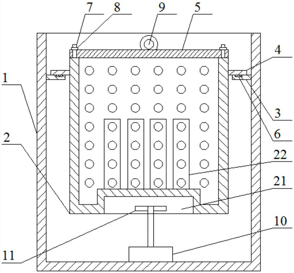
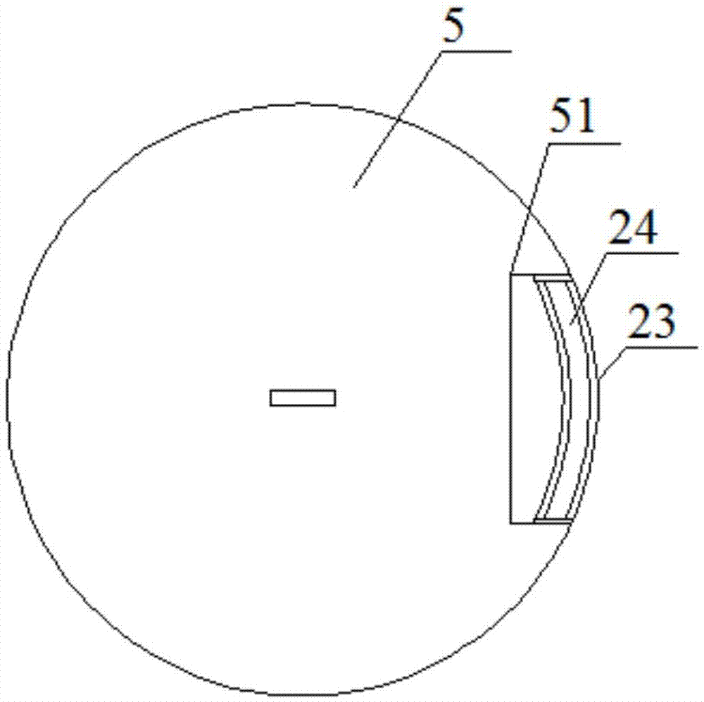
[0030] Such as figure 1 and figure 2 As shown, the self-circulation soaking processor includes an outer barrel 1, an inner barrel 2, an outer fixing ring 3, an inner fixing ring 4, and an inner barrel cover 5; the outer fixing ring 3 is fixed on the inner surface of the outer barrel 1, and the inner fixing ring 4 is fixed on The outer surface of the inner barrel 2, the inner barrel 2 is arranged in the outer barrel 1, and the inner barrel 2 is suspended on the outer fixing ring 3 through the inner fixing ring 4; the inner barrel cover 5 is arranged on the top of the inner barrel 2; the inner barrel 2 is made of a perforated plate; Concave inwardly to form accommodating chamber 21, the top of accommodating chamber 21 is inwardly recessed to form a plurality of upwardly protruding inward concave sections 22; it also includes a motor 10 arranged at the bottom of outer tub 1, and the output end of motor 10 is upward; The output end of the motor 10 is connected to the impeller 11...

Embodiment 2

[0036] Such as figure 1 As shown, on the basis of Embodiment 1, this embodiment further includes a sealing ring 6 disposed on the upper surface of the outer fixing ring 3 , and the sealing ring 6 is in contact with the lower surface of the inner fixing ring 4 .

[0037] A sealing ring 6 is provided to prevent soaking liquid from overflowing from between the outer fixing ring 3 and the inner fixing ring 4 .

Embodiment 3

[0039] Such as figure 1 As shown, on the basis of Embodiment 1, the present embodiment also includes a plurality of screw rods 7 arranged vertically on the top of the inner barrel 2, and the screw rods 7 run through the inner barrel cover 5; The inner barrel cover 5 is pressed on the top of the inner barrel 2.

[0040] The inner barrel cover 5 is pressed tightly on the top of the inner barrel 2 to avoid the flow of the soaking liquid and the inner barrel cover 5 is pushed away, thereby improving the working reliability.


PUM


Abstract

The invention discloses a self-circulation soaking processor; the outer fixing ring is fixed on the inner surface of the outer barrel, the inner fixing ring is fixed on the outer surface of the inner barrel, the inner barrel is arranged in the outer barrel, and the inner barrel is suspended from the outer fixing ring through the inner fixing ring above; the inner barrel cover is set on the top of the inner barrel; the inner barrel is made of a perforated plate; the bottom of the inner barrel is recessed inwardly to form a receiving chamber, and the top of the receiving chamber is recessed inwardly to form a plurality of upwardly protruding inner concave sections; it is also included at the bottom of the outer barrel It also includes an impeller connected to the output end of the motor, and the impeller is located in the accommodating cavity; the top of the inner barrel is provided with a slot extending to the bottom of the inner barrel, the plugboard is inserted into the slot, and the inner barrel cover is provided with an opening corresponding to the slot . The invention can conveniently pour out the treated crops. The motor drives the impeller to rotate, and the impeller drives the soaking liquid in multiple concave sections to move, and the soaking liquid drives the crops in the inner barrel to move, so that the crops in all parts of the inner barrel can fully contact with the soaking liquid.

Description

technical field [0001] The invention relates to a crop processing equipment. Background technique [0002] Some crops (such as rice, tartary buckwheat, etc.) need to be soaked before processing. Currently in the crop processing process, the crops are placed in barrels and soaked in the barrels. After the soaking is completed, the soaking liquid in the barrel needs to be poured out before the crops can be taken out, which is inconvenient to operate. At the same time, when the crops are soaked, the soaking liquid is in a static state, resulting in insufficient contact between the crops and the soaking liquid, which affects the treatment effect. Contents of the invention [0003] The purpose of the present invention is to overcome the deficiencies of the prior art and provide a self-circulating soaking processor. [0004] The object of the present invention is achieved through the following technical solutions: [0005] Self-circulation soaking processor, including outer ...

Claims


Application Information

Patent Timeline
IPC IPC(8): A23L7/10B65D81/22B65D77/04
CPCB65D81/22B65D77/0493
Inventor 郑起谋
Owner CHONGQING XIANGYI AGRI DEV
Why Eureka
Try Eureka