Puncture needle positioning device

A positioning device and puncture needle technology, applied in the direction of puncture needles, trocars, medical science, etc., can solve the problem of not being able to grasp the angle of the puncture needle, not having the ability to adjust the angle of the puncture needle, and the guiding device cannot assist doctors in judging the needle entry point The exact position and other issues can be avoided to avoid contamination and infection, reduce operation time, and improve efficiency and accuracy

Active Publication Date: 2017-06-16
METAL INDS RES & DEV CENT +1
3 Cites 6 Cited by

AI-Extracted Technical Summary

Problems solved by technology

Therefore, if the patient has some small movements or displacements, the guiding device still cannot assist the doctor in judging the exact position of the needle entry point
In addition,...

Method used

[0031] For example, the assembling method shown in FIG. 1 is assembled for the surgical requirements on the left side of the body. The first slide rail 421 is disposed in the positioning portion 425 a near the right side of the positioning block 425 , while the second slide rail 423 and the entire angle adjustment structure 440 are disposed on the left side of the first slide rail 421 . In this way, the doctor can determine the insertion position of the puncture needle 200 by adjusting the first slider 422 and the second slider 424 . Then, the needle entry angle of the puncture needle 200 is adjusted by ...

Abstract

The invention discloses a puncture needle positioning device suitable for adjusting and positioning a puncture needle. The puncture needle positioning device comprises a back frame and a positioning mechanism, the positioning mechanism is arranged on the back frame and comprises a position adjusting structure and an angle adjusting structure, the positioning adjusting structure can move relative to the back frame in the first and second directions and comprises a first needle penetrating piece, the angle adjusting structure is arranged on the position adjusting structure, can move relative to the position adjusting structure and comprises a second needle penetrating piece, and the puncture needle can penetrate the second needle penetrating piece and the first needle penetrating piece. In this way, the step of positioning the puncture needle can be simplified through the puncture needle positioning device, and the positioning accuracy of the puncture needle can be substantially improved.

Application Domain

Technology Topic

Needle positionSurgery

Image

  • Puncture needle positioning device
  • Puncture needle positioning device
  • Puncture needle positioning device

Examples

  • Experimental program(1)

Example Embodiment

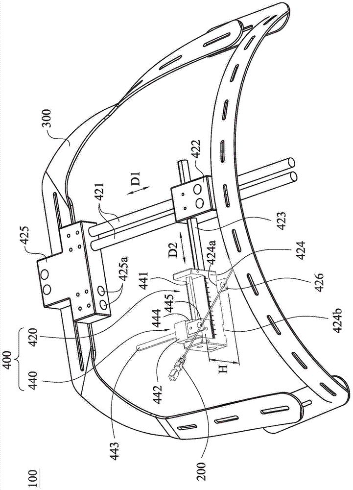
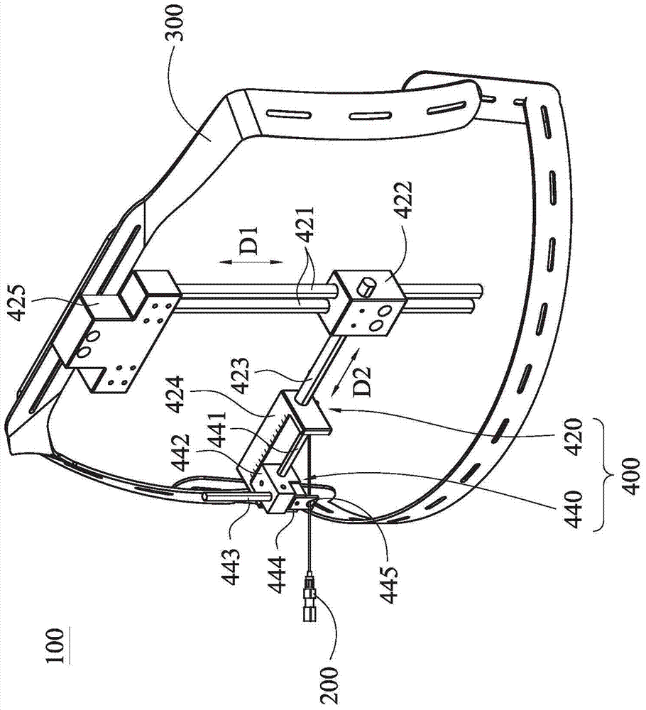
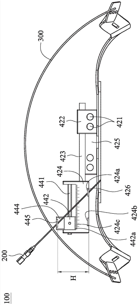
[0022] Please also refer to figure 1 and figure 2 , which are device schematic diagrams respectively showing two different angles of a puncture needle positioning device according to an embodiment of the present invention. The puncture needle positioning device 100 of this embodiment can be directly worn by the patient, and the doctor can operate the puncture needle positioning device 100 to adjust and position the puncture needle 200, thereby preventing the patient from moving relative to the puncture needle positioning device 100, and further The needle insertion position and needle insertion angle of the puncture needle 200 are determined to achieve the purpose of improving the accuracy and success rate of the puncture operation.
[0023] Please continue to refer to figure 1 and figure 2 , the puncture needle positioning device 100 mainly includes a back frame 300 and a positioning mechanism 400 . In this embodiment, the back frame 300 is mainly worn on the human body, and its shape and size can be adjusted according to different body types. The positioning mechanism 400 is disposed on the back frame 300 and includes a position adjustment structure 420 and an angle adjustment structure 440 . The position adjusting structure 420 mainly includes a first sliding rail 421 , a first sliding block 422 , a second sliding rail 423 and a second sliding block 424 . The first sliding rail 421 can be fixed on the back frame 300 through the positioning block 425 . Moreover, the extension direction of the first slide rail 421 is parallel to the first direction D1. The first sliding block 422 is disposed on the first sliding rail 421 and can slide relative to the back frame 300 along the first direction D1 on the first sliding rail 421 . like figure 1 As shown, in an example, the first sliding rail 421 can be a rod body, and is fixed on the positioning block 425 . In some embodiments, the positioning block 425 has a plurality of positioning portions 425a. In this way, the fixed position of the first sliding rail 421 on the positioning portion 425a can be changed to meet different usage requirements.
[0024] like figure 1 and figure 2 As shown, the second sliding rail 423 is passed through the first sliding block 422 , and the extending direction of the second sliding rail 423 is parallel to the second direction D2. In an example, the second slide rail 423 can also be a rod body. The second sliding block 424 is disposed on the second sliding rail 423 and can slide relative to the first sliding block 422 along the second direction D2. Accordingly, by changing the positions of the first slider 422 and the second slider 424 , the insertion position of the puncture needle 200 can be determined.
[0025] In this embodiment, the position adjusting structure 420 further includes a first needle piercing piece 426 . The first needle piercing piece 426 is detachably arranged on the second sliding block 424 . The first needle piercing piece 426 is mainly used to guide the puncture needle 200 to penetrate the human body from the correct needle insertion position. In one embodiment, the first needle piercer 426 is a detachable and disposable design, which can be screwed or engaged on the second sliding block 424 . In other embodiments, the bottom of the second slider 424 is provided with a first groove 424 a and a second groove 424 b. Thereby, the first needle piercing piece 426 can be selectively fixed in the first groove 424 a and the second groove 424 b according to requirements.
[0026] Please continue to refer to figure 1 and figure 2 , the angle adjustment structure 440 is disposed on the position adjustment structure 420 and can move relative to the position adjustment structure 420 . In one embodiment, the angle adjusting structure 440 includes a third sliding rail 441 , a third sliding block 442 , a fourth sliding rail 443 and a fourth sliding block 444 . In one embodiment, the second sliding block 424 has a U-shaped structure, and the third sliding rail 441 can be disposed on the second sliding block 424 . In other embodiments, the extending direction of the third sliding rail 441 is parallel to the second direction D2. like figure 2 As shown, the third sliding block 442 is disposed on the third sliding rail 441 and can slide relative to the second sliding block 424 along the second direction D2.
[0027] Please continue to refer to figure 2 , the fourth sliding rail 443 passes through the third sliding block 442 , and the extending direction of the fourth sliding rail 443 is parallel to the first direction D1. The fourth sliding block 444 is disposed on the fourth sliding rail 443 and can move relative to the third sliding block 442 along the first direction D1. In this embodiment, the angle adjusting structure 440 further includes a second needle piercing piece 445 . The second needle piercing piece 445 is detachably arranged on the fourth sliding block 444 . Thereby, by changing the positions of the third slider 442 and the fourth slider 444 , the relative positions of the second needle piercing piece 445 and the first needle piercing piece 426 can be changed. In one embodiment, the second needle piercer 445 is a detachable and disposable design, which can be screwed or engaged on the fourth sliding block 444 . In some examples, the third sliding rail 441 and the fourth sliding rail 443 can also be rod bodies.
[0028] Please continue to refer to figure 1 and figure 2 , the puncture needle 200 can be sequentially passed through the second needle piercer 445 and the first needle piercer 426 . Please also refer to image 3 , which is a side view illustrating a puncture needle positioning device according to an embodiment of the present invention. It should be understood that since the second needle piercing piece 445 is arranged on the fourth slider 444, and the first needle piercing piece 426 is arranged on the bottom of the second slider 424, so the first needle piercing piece 426 and the second needle piercing piece There is a distance H between the pins 445 . Therefore, by adjusting the relative position of the second needle piercing piece 445 and the first needle piercing piece 426 , the effect of adjusting the needle penetration angle of the puncture needle 200 can be achieved.
[0029] like image 3As shown, in one embodiment, the second slider 424 is provided with a first scale 424c, and the third slider 442 is provided with a second scale 442a corresponding to the first scale 424c. Thereby, when the doctor adjusts the third slider 442 , he can refer to the first scale 424 c and the second scale 442 a to grasp the moving distance of the third slider 442 .
[0030] It should be understood that the puncture needle positioning device 100 of the present invention adopts a modular design, which can change the wearing mode of the back frame 300 (for example, wearing it forward or backward), or change the assembly mode of the positioning mechanism 400 according to requirements, so as to achieve The purpose of meeting different surgical needs. For example, changing the wearing method of the back frame 300 can make the positioning mechanism 400 face the front, back or side of the body, and changing the assembly method of the positioning mechanism 400 can make the entire angle adjustment structure be located on the left or right side of the body.
[0031] For example, if figure 1 The assembly shown is for surgical needs on the left side of the body. The first slide rail 421 is disposed in the positioning portion 425 a near the right side of the positioning block 425 , while the second slide rail 423 and the entire angle adjustment structure 440 are disposed on the left side of the first slide rail 421 . In this way, the doctor can determine the insertion position of the puncture needle 200 by adjusting the first slider 422 and the second slider 424 . Then, the needle entry angle of the puncture needle 200 is adjusted by adjusting the third slider 442 and the fourth slider 444 , so as to accurately locate the needle entry angle position and the needle entry angle of the puncture needle.
[0032] And when the doctor needs to operate on the right side of the body, the first slide rail 421 can be installed in the positioning portion 425 a near the left side of the positioning block 425 . Then install the second slide rail 423 and the entire angle adjustment structure 440 on the right side of the first slide rail 421 . In this way, after adjusting the first slider 422 and the second slider 424 to determine the insertion position of the puncture needle 200, the insertion position of the puncture needle 200 can be adjusted by adjusting the third slider 442 and the fourth slider 444. needle angle to achieve the same purpose as previously described.
[0033] It can be seen from the above-mentioned embodiments of the present invention that the puncture needle positioning device of the present invention is wearable, so it can ensure that the computer tomography image, patient position and positioning mechanism location consistency. Thereby, the efficiency and accuracy of puncture and the success rate of operation can be improved.
[0034] From the above-mentioned embodiments of the present invention, it can be known that the puncture needle positioning device of the present invention has a modular structure design, which can provide doctors with the ability to change the assembly method of the positioning mechanism according to the image results of computer tomography and surgical requirements, thereby simplifying the structure and operation. Simple purpose, which can reduce operation time.
[0035] From the above-mentioned embodiments of the present invention, it can be known that the first needle piercer and the second needle piercer of the puncture needle positioning device of the present invention are designed to be detachable and disposable, thereby allowing doctors to replace the first needle piercer with a new one after each operation. The needle piece and the second needle piercer achieve the purpose of hygiene and avoid contamination and infection.
[0036] Although the present invention has been disclosed above in terms of implementation, it is not intended to limit the present invention. Any person skilled in the art may make various changes and modifications without departing from the spirit and scope of the present invention. Therefore, the protection of the present invention The scope is to be determined as defined by the claims.

PUM

no PUM

Description & Claims & Application Information

We can also present the details of the Description, Claims and Application information to help users get a comprehensive understanding of the technical details of the patent, such as background art, summary of invention, brief description of drawings, description of embodiments, and other original content. On the other hand, users can also determine the specific scope of protection of the technology through the list of claims; as well as understand the changes in the life cycle of the technology with the presentation of the patent timeline. Login to view more.

Similar technology patents

Classification and recommendation of technical efficacy words

  • Simple structure and operation
  • Improve efficiency and accuracy

Rotary type vehicle carrying board one-position for two-car parking device

InactiveCN101033653AReduce channel areaSimple structure and operationParkingsElectric machineryVehicle frame
Owner:朱建华

Overturn-preventing falling-preventing attached lifting scaffold

InactiveCN105401715ASimple structure and operationBuilding support scaffoldsEngineeringSelf weight
Owner:ZHONGYIFENG CONSTR GRP

Organic vacuum evaporation source

PendingCN106987809ASimple structure and operationEasy to produceVacuum evaporation coatingSputtering coatingPhysicsThermocouple Wire
Owner:DALIAN JIAOTONG UNIVERSITY

Household portable blood glucose detector and detection method

PendingCN109846493AEasy to useSimple structure and operationDiagnostic recording/measuringSensorsGlucose meter deviceEngineering
Owner:HARBIN UNIV
Why Eureka
Try Eureka