
A two-way locking mechanism

A locking mechanism and locking technology, applied in metal processing equipment, metal processing, manufacturing tools, etc., can solve problems such as energy waste and work efficiency cannot be improved

Active Publication Date: 2018-10-30
BOZHON PRECISION IND TECH CO LTD
View PDF8 Cites 0 Cited by
  • Summary
  • Abstract
  • Description
  • Claims
  • Application Information

AI Technical Summary

Problems solved by technology

[0003] The above-mentioned screw screwing device is used to drive the driving mechanism (including lifting slider and L-shaped mounting plate) for driving the electric screwdriver to go up and down. It drives the electric screwdriver to descend, which is the working stroke, and drives the electric screwdriver to rise and reset, which is non-working. In this way, half of the actions made by the driving mechanism are working strokes, and the other half are non-working strokes, which not only causes waste of energy, but also does not improve work efficiency.

Method used


Image

  • A two-way locking mechanism
  • A two-way locking mechanism
  • A two-way locking mechanism

Examples


Embodiment Construction

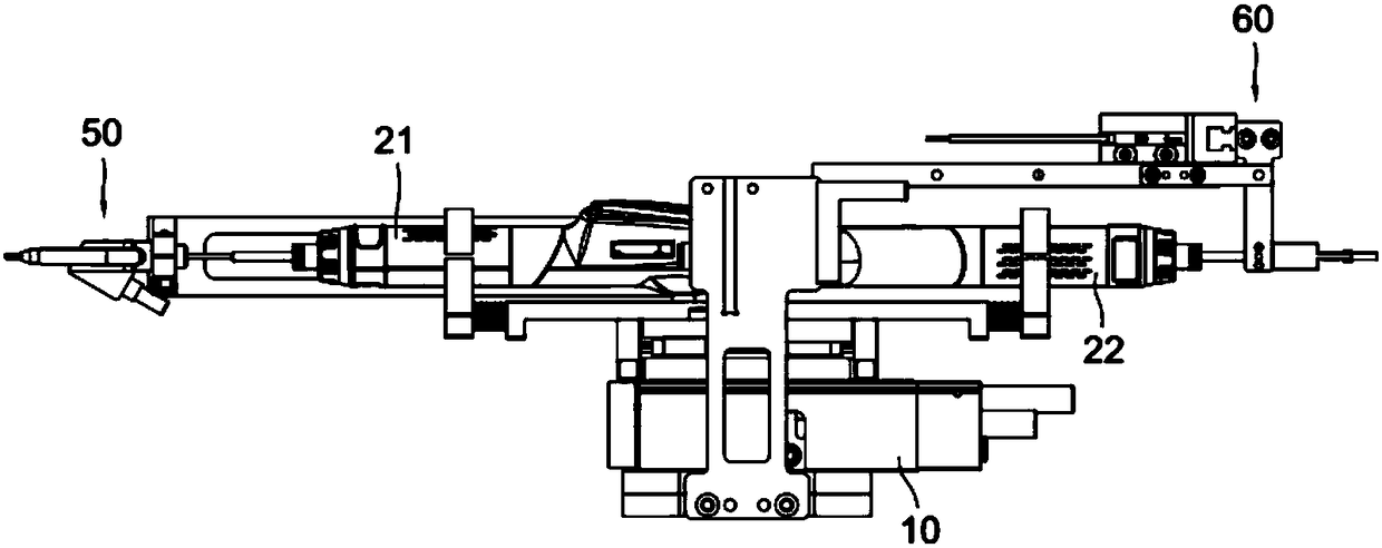
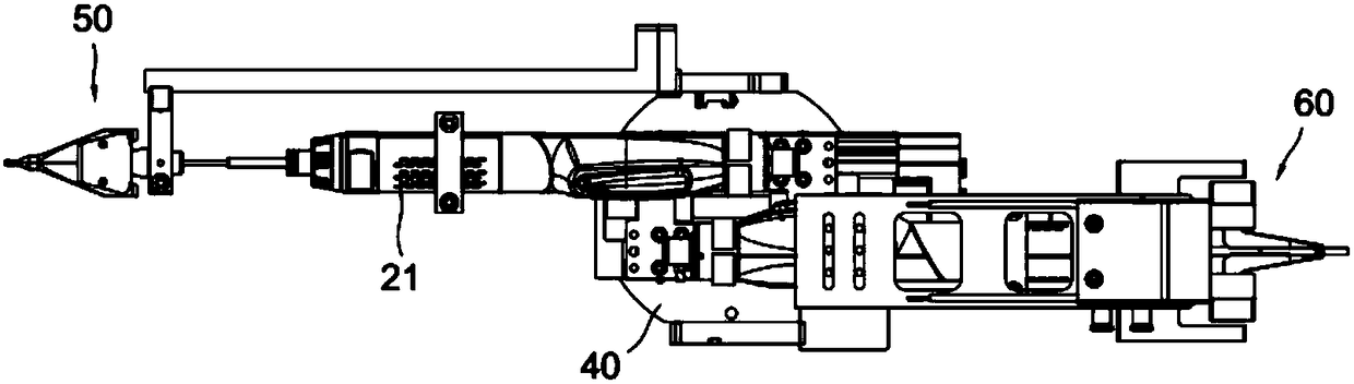
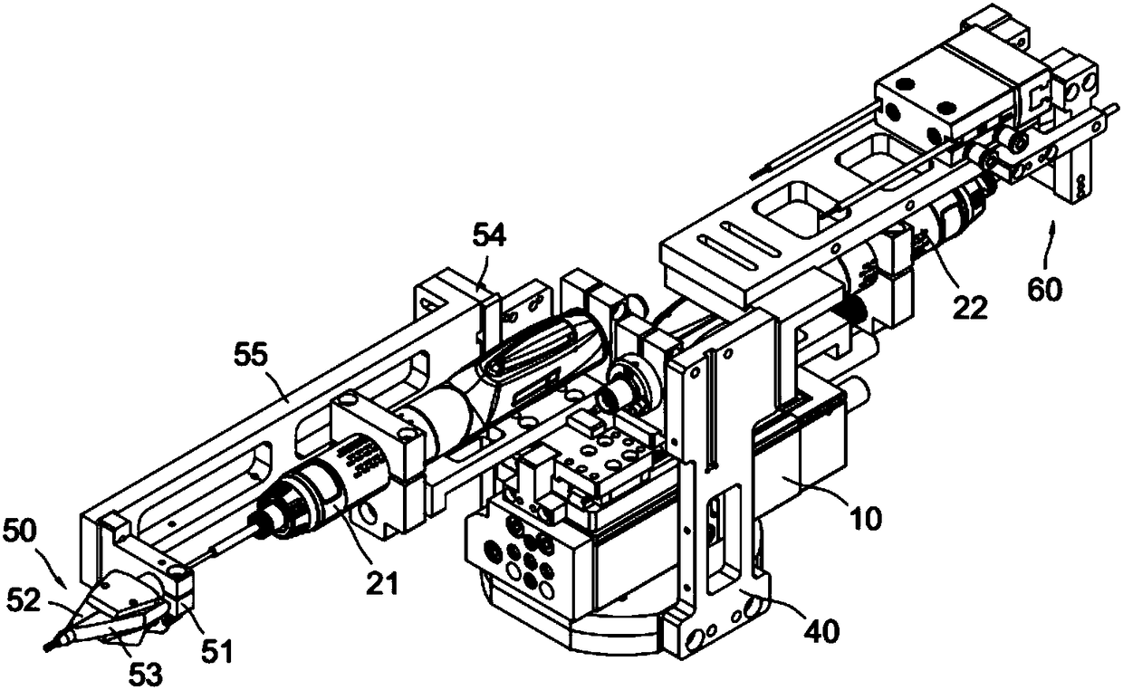
[0029] combine Figure 1 to Figure 4 , a two-way locking mechanism, including two locking tools installed on the driving mechanism, and the moving directions of the two locking tools are opposite when they work. The two locking tools are respectively a first locking tool and a second locking tool.

[0030] combine Figure 3 to Figure 6 , the drive mechanism includes a cylinder 10 mounted on the frame 40, a base plate 14 mounted on the cylinder piston, a first slide rail 15 and a second slide rail 16 mounted on the base plate, and slidingly fitted on the first slide rail The first sliding block 11 and the second sliding block 12 slidingly fitted on the second sliding rail, the first locking tool 21 is installed on the first sliding block, and the second locking tool 22 is installed on the second sliding block, A telescopic spring 13 is arranged between the first slider and the second slider. A first stopper 17 and a second stopper 18 are arranged on the base plate, and the f...


PUM


Abstract

A bidirectional locking mechanism comprises two locking tools installed on a driving mechanism. The moving directions of the two locking tools are opposite when the locking tools operate. The advancing and receding of the driving mechanism can drive the corresponding locking tool to operate. The advancing and receding of the driving mechanism are operating strokes, no stroke waste occurs, the utilization rate of the driving mechanism is improved, and the bidirectional locking mechanism is simple and convenient to use and compact in structure.

Description

technical field [0001] The invention relates to the technical field of screw locking, in particular to a screw locking mechanism. Background technique [0002] A screw gun is a locking tool for locking screws. The invention patent application document with the application publication number CN 105750894 A discloses a screw-in device for a plug-in assembly machine, in which the lifting slider cooperates with the slide rail, and four guide columns are fixed on the horizontal plate of the L-shaped mounting plate , the guide post passes through the guide plate downwards, the guide post between the L-shaped mounting plate and the guide plate is covered with a buffer spring, and the electric screwdriver is installed on the L-shaped mounting plate. The above-mentioned buffer spring in the screw-in device is used to compensate the locking process of the screw-in device. [0003] The above-mentioned screw screwing device is used to drive the driving mechanism (including lifting sli...

Claims


Application Information

Patent Timeline
Patent Type & Authority Patents(China)
IPC IPC(8): B23P19/06
CPCB23P19/06
Inventor 吕绍林陈小刚姜汉豪饶元张书天
Owner BOZHON PRECISION IND TECH CO LTD
Learn More