

Floor mopping robot
A sweeping robot and robot body technology, applied in the field of sweeping robots, can solve the problems of large force of side brushes, difficult replacement of side brushes, and large force of side brushes, so as to reduce cleaning frequency, avoid potential safety hazards, and prolong service life Effect
- Summary
- Abstract
- Description
- Claims
- Application Information
AI Technical Summary
Problems solved by technology
Method used
Image

Examples
Embodiment 1
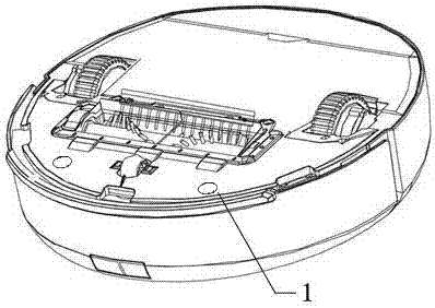
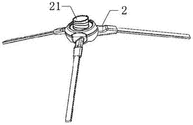
[0040] Such as Figure 1 to Figure 9 As shown, a sweeping robot includes a robot body. The interior of the robot body adopts the settings of the prior art, wherein the internal connection relationship of the robot body is not modified, and a through hole 1 is opened under the rotating part in the robot body. The number is several, and each through hole 1 is detachably connected with a side brush 2.
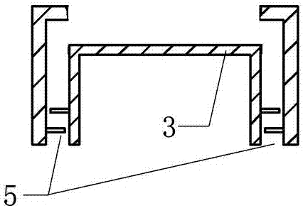
[0041] The through hole 1 is provided with connectors 3 at intervals. The outer wall of the connector 3 does not contact the inner wall of the through hole 1. The connector 3 has a certain movable space in the through hole 1. The end of the connector 3 near the rotating part is closed, and the other end is closed. Opening, the connecting head 3 can move a certain distance in the vertical direction in the through hole 1 and then connect with the rotating part, and the connecting head 3 is detachably connected with the side brush 2 . A limiting member 5 is provided between the inne...
Embodiment 2
[0045] Such as Figure 5 As shown, the technical solution adopted in Embodiment 1 is roughly the same, the difference is that an extension 4 is provided at one end of the through hole 1, and the extension 4 is arranged near the opening end of the connector 3, and the end of the extension 4 is connected to the connector. 3 inner walls are on the same vertical line, thereby completely restricting the connector 3 inside the through hole 1. Between the inner wall of the extension part 4 and the opening at the top of the connector 3, a snapping part 6 is provided. It is tooth-shaped, and when the engaging part of the connecting head 3 is in contact with the engaging part of the extension part 4, the tooth shape can fit, thereby restricting the movement of the connecting head 3 in the horizontal direction. At this time, the limiting member 5 may or may not be provided between the through hole 1 and the side wall of the connector 3 .
[0046] Such as Image 6 As shown, an extensio...
Embodiment 3
[0048] Such as image 3 , Figure 4 , Image 6 , Figure 7 Shown are the implementation forms of several limiting parts 5 . image 3 The middle limiting part is a convex edge arranged along the horizontal direction, the width of the first limiting part and the second limiting part is slightly smaller than the size of the gap between the connector 3 and the through hole 1, and the first limiting part and the second limiting part are symmetrically staggered It is set that the first part of the limit is closer to the opening of the connector 3 than the second part of the limit.
[0049] Figure 4 The middle limiting part is a conical protrusion with a slope, and the first limiting part and the second limiting part are also arranged symmetrically and staggeredly. The inclined planes of the two limiting parts will form surface contact.
[0050] Image 6 with Figure 7 The middle limit piece is a bump set along the vertical direction, the first limit part and the second limi...
PUM
 Abstract
Description
Claims
Application Information