
Back gauge for bending machine and bending machine

A technology of bending machine and back gauge, applied in the field of bending machines, can solve the problem of inaccurate back gauge, and achieve the effect of accurate position and accurate gauge

Inactive Publication Date: 2017-06-20
郭敏青
View PDF7 Cites 4 Cited by
  • Summary
  • Abstract
  • Description
  • Claims
  • Application Information

AI Technical Summary

Problems solved by technology

The position and function of the backgauge, the traditional backgauge is split, install two line rails, the position of the two line rails will change during installation; this will cause the backgauge to be inaccurate

Method used


Image

  • Back gauge for bending machine and bending machine
  • Back gauge for bending machine and bending machine
  • Back gauge for bending machine and bending machine

Examples


Embodiment Construction

[0022] In order to make the purpose, technical solutions and advantages of the embodiments of the present invention clearer, the technical solutions in the embodiments of the present invention will be clearly and completely described below in conjunction with the drawings in the embodiments of the present invention. Obviously, the described embodiments It is a part of embodiments of the present invention, but not all embodiments. Elements and features described in one drawing or one embodiment of the present invention may be combined with elements and features shown in one or more other drawings or embodiments. It should be noted that representation and description of components and processes that are not related to the present invention and known to those of ordinary skill in the art are omitted from the drawings and descriptions for the purpose of clarity. Based on the embodiments of the present invention, all other embodiments obtained by persons of ordinary skill in the ar...


PUM


Abstract

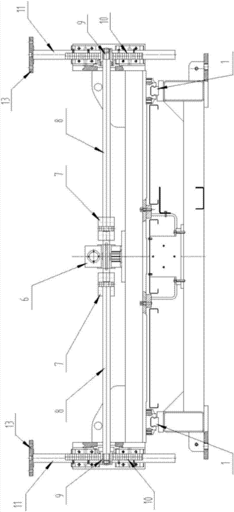
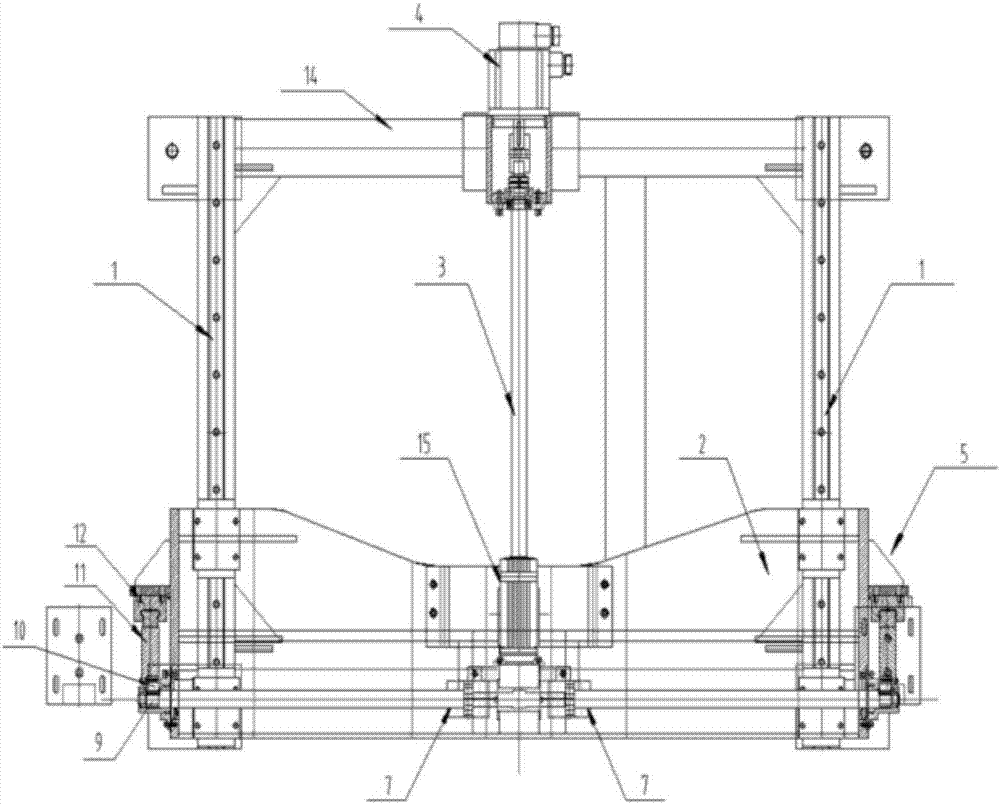
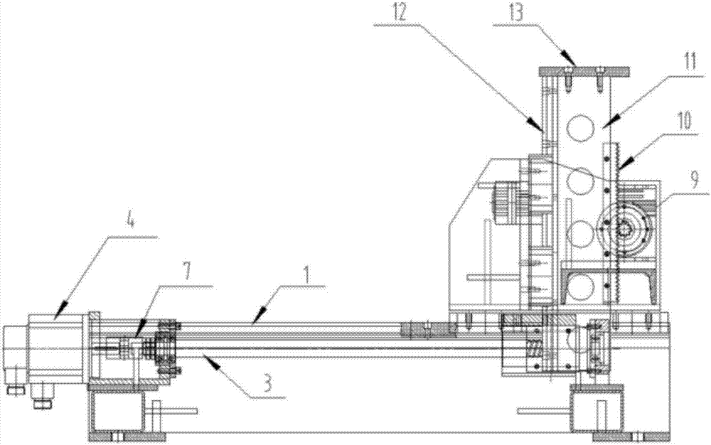
The invention discloses a back gauge for a bending machine and the bending machine. The back gauge for the bending machine comprises two linear guide rails parallel to each other; the two linear guide rails are provided with a carriage; the carriage can move on the two linear guide rails and is connected with a screw rod; the screw rod is connected with a servo motor capable of moving front and back; and the carriage is provided with two lifting devices. According to the back gauge for the bending machine and the bending machine, a frame-type integrated structure is adopted, the two linear guide rails are parallel, the effect that the guide rails are accurate in position and cannot deviate is ensured through the integrated structure, and accordingly, the accuracy of the back gauge is achieved.

Description

technical field [0001] The invention relates to a bending machine, in particular to a backgauge used for the bending machine and the bending machine. Background technique [0002] The bending machine is a machine capable of bending thin plates. It includes a bracket, a workbench, a clamping plate and a backgauge. The workbench is placed on the bracket. The workbench is composed of a base and a pressure plate. Tight board connected. The position and function of the backgauge, the traditional backgauge is split, install two line rails, the position of the two line rails will change during installation; this will lead to inaccurate backgauge. Contents of the invention [0003] A brief overview of the invention is given below in order to provide a basic understanding of some aspects of the invention. It should be understood that this summary is not an exhaustive overview of the invention. It is not intended to identify key or critical parts of the invention nor to delineate...

Claims


Application Information

Patent Timeline
IPC IPC(8): B21D43/00B21D5/00
CPCB21D43/003B21D5/002
Inventor 郭敏青
Owner 郭敏青
Learn More