Automatic discharging and positioning device for punching and control method

A positioning device and automatic cutting technology, applied in the field of parts production, can solve the problems of increasing the labor force of the production line and reducing the work efficiency of the production process, so as to improve the production quality, reduce the management pressure and labor cost, and improve the product quality and production efficiency. Effect

Active Publication Date: 2017-06-20
广东佛智芯微电子技术研究有限公司
View PDF9 Cites 3 Cited by
  • Summary
  • Abstract
  • Description
  • Claims
  • Application Information

AI Technical Summary

Problems solved by technology

[0003] In the production process of the filter element lock cover, the processes of workpiece handling, transfer, feeding arrangement, positioning, etc. need to be completed by manpower, especially between the two processes of stamping blanking and thread processing, the workpiece is manufactured by the punching machine to produce the filter element lock. After the initial workpiece of the cover, the workpiece often falls freely into the material frame after stamping, and the work that falls into the material frame in this way is in an irregularly scattered state, so when transferring the scattered workpieces to the thread processing process, it is necessary The workpieces are picked up one by one from the material box by manpower, and then transferred to the thread processing mold for processing. This production method causes additional labor on the production line and reduces the work efficiency of the entire production process.

Method used


Image

  • Automatic discharging and positioning device for punching and control method
  • Automatic discharging and positioning device for punching and control method
  • Automatic discharging and positioning device for punching and control method

Examples


Embodiment Construction

[0035] The following will clearly and completely describe the technical solutions in the embodiments of the present invention with reference to the accompanying drawings in the embodiments of the present invention. Obviously, the described embodiments are only part of the embodiments of the present invention, not all of them. Based on the embodiments of the present invention, all other embodiments obtained by persons of ordinary skill in the art without creative efforts fall within the protection scope of the present invention.

[0036] It should be noted that if there is a directional indication (such as up, down, left, right, front, back...) in the embodiment of the present invention, the directional indication is only used to explain the position in a certain posture (as shown in the accompanying drawing). If the specific posture changes, the directional indication will also change accordingly.

[0037] In addition, if there are descriptions involving "first", "second" and ...


PUM


Abstract

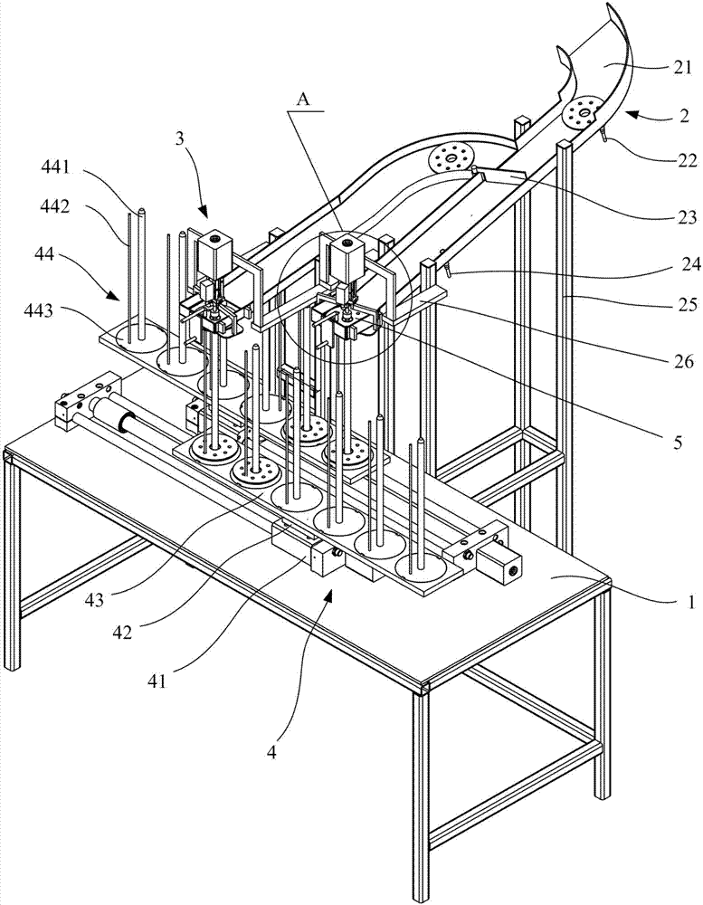
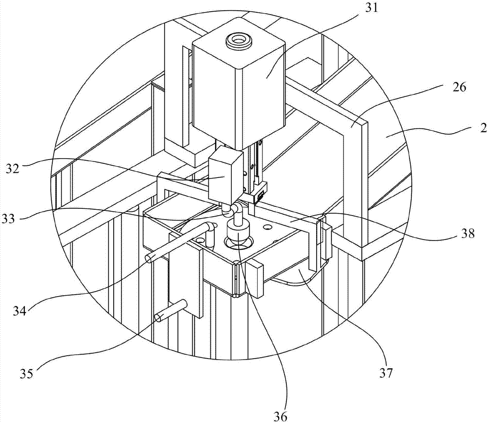
The invention discloses an automatic discharging and positioning device for punching. The automatic discharging positioning device comprises a material receiving table, a material receiving mechanism, a detection positioning mechanism, a feeding mechanism and a main system circuit. The material receiving mechanism is installed on the top face of the material receiving table. The detection positioning mechanism is arranged above the material receiving mechanism. One end of the feeding mechanism is closed to a punching machine, and the other end of the feeding mechanism is close to the detection positioning mechanism. The invention further provides a control method. The feeding mechanism conveys workpieces to the detection positioning mechanism through the perpendicular height difference of the two ends, and the detection positioning mechanism and the material receiving mechanism are matched to position and stack the workpieces. According to the technical scheme, operation workers can be reduced for a production line, labor force is liberated, and enterprise management pressure and labor cost are reduced; meanwhile, a feeding groove is adopted for conducting directional conveying and stacking the workpieces through a stacking frame in a concentrated manner according to a certain rule, surface damage of the workpieces can be reduced, and the production quality of the products is improved; and in addition, the workpiece are stacked in the same direction, and the workpieces can be positioned and machined rapidly in the subsequent processes.

Description

technical field [0001] The invention relates to the technical field of parts production, in particular to a stamping automatic blanking positioning device and a control method. Background technique [0002] In the production of auto parts, the filter element lock cover is a relatively important part of the automobile cartridge filter element, which can lock the filter cotton core and play a role in the installation and positioning of the filter element. The production process of the filter element lock cover needs to go through multiple processes such as stamping, punching, blanking, and thread processing. [0003] In the production process of the filter element lock cover, the processes of workpiece handling, transfer, feeding arrangement, positioning, etc. need to be completed by manpower, especially between the two processes of stamping blanking and thread processing, the workpiece is manufactured by the punching machine to produce the filter element lock. After the init...

Claims


Application Information

Patent Timeline
Patent Type & Authority Applications(China)
IPC IPC(8): B21D43/20B21D43/00B21D45/00B21D53/88
CPCB21D43/003B21D43/20B21D45/00B21D53/88
Inventor 郭子龙谢克庆邓来华温春阳
Owner 广东佛智芯微电子技术研究有限公司
Why Eureka
Try Eureka