Riveting device for pressing disk in cover assembly

A pressure plate and riveting technology, which is applied in the assembly field of the clutch cover assembly, can solve problems such as product and positioning looseness or tightness, troublesome production, lower production efficiency and product quality, so as to improve work efficiency, avoid positioning deviation, The effect of avoiding errors

Inactive Publication Date: 2017-06-20
WUHU DAJIE CLUTCH
View PDF7 Cites 4 Cited by
  • Summary
  • Abstract
  • Description
  • Claims
  • Application Information

AI Technical Summary

Problems solved by technology

[0002] At present, the assembly mold of the pressure plate of the cover assembly needs to be designed and positioned in conjunction with the pressure plate. The center hole of the pressure plate is machined. Due to the machining accuracy of the processing machine and the level of the operator, different batches of products will have a certain degree of Even if it is the same batch of products, the center hole of the pressure plate cannot guarantee the accuracy and deviation of all products at the same level, which will bring certain problems to the assembly of the pressure plate, such as the product and positioning are too loose or Tight, even the product cannot match the positioning
When the frequency of this situation is very high, it will bring a lot of trouble to the production, reduce the production efficiency and product quality

Method used


Image

  • Riveting device for pressing disk in cover assembly
  • Riveting device for pressing disk in cover assembly
  • Riveting device for pressing disk in cover assembly

Examples


Embodiment 1

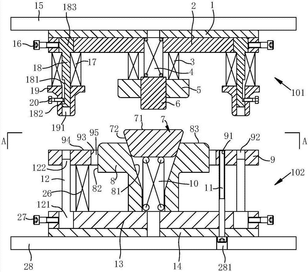
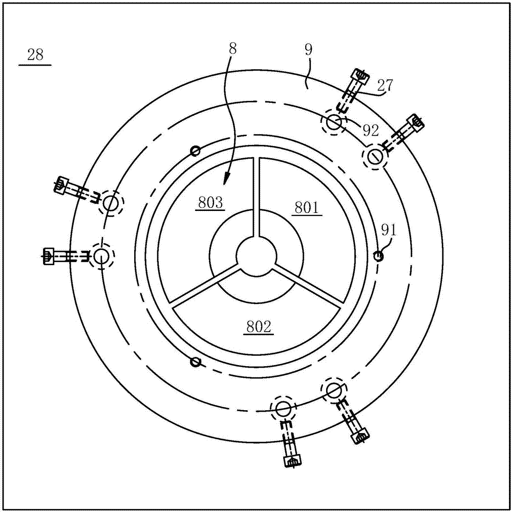
[0028] refer to figure 1 and figure 2 , a riveting device for the pressure plate in the cover assembly, the upper cover plate 15 and the lower cover plate 28 are arranged up and down, and the upper riveting device 101 fixed on the upper cover plate is arranged on the lower side of the upper cover plate. The upper side of the plate is provided with a lower riveting device 102 .

[0029] The upper riveting device 101 and the lower riveting device 102 correspond up and down, and the upper riveting device includes a horizontally arranged upper fixing plate 2 and a positioning assembly and an upper riveting assembly installed on the lower side of the upper fixing plate. The upper fixing plate 2 is fixed on the lower side of the upper cover plate 15, and an upper rubber pad 1 is placed between the upper fixing plate and the upper cover plate.

[0030] The positioning assembly includes a first elastic piece 4 and a second elastic piece 3 fixedly arranged on the upper fixing plate ...


PUM


Abstract

The invention discloses a riveting device for a pressing disk in a cover assembly. The riveting device for the pressing disk in the cover assembly comprises an upper riveting device and a lower riveting device; the upper riveting device comprises a horizontally arranged upper fixing plate, a positioning assembly and an upper riveting assembly, and the positioning assembly and the upper riveting assembly are installed on the lower side of the upper fixing plate; and the lower riveting device comprises a horizontally arranged lower fixing plate, a pressing disk adjusting unit, a lower riveting assembly and a pre-tightening plate, and the pressing disk adjusting unit, the lower riveting assembly and the pre-tightening plate are installed on the upper side of the lower fixing plate. The upper riveting assembly and the lower riveting assembly comprise punch sets of the same number. In the riveting device, the set number of the upper riveting punch sets corresponds to the installing number of conveying belts in the cover assembly; each conveying belt corresponds to one upper riveting punch set; when the pressing disk is installed, connection of the conveying belts between a cover and the pressing disk can be completed at a time, the tedious process that in the prior art, when the pressing disk is installed, it is needed to firstly install the conveying belts on the cover and then install the conveying belts on the pressing disk is avoided, and the work efficiency is improved.

Description

technical field [0001] The invention relates to the technical field of clutch middle cover assembly assembly, in particular to an assembly device for a pressure plate in a cover assembly, which is used to improve work efficiency and product precision. Background technique [0002] At present, the assembly mold of the pressure plate of the cover assembly needs to be designed and positioned in conjunction with the pressure plate. The center hole of the pressure plate is machined. Due to the machining accuracy of the processing machine and the level of the operator, different batches of products will have a certain degree of Even if it is the same batch of products, the center hole of the pressure plate cannot guarantee the accuracy and deviation of all products at the same level, which will bring certain problems to the assembly of the pressure plate, such as the product and positioning are too loose or If it is tight, it may even appear that the product cannot match the posit...

Claims


Application Information

Patent Timeline
Patent Type & Authority Applications(China)
IPC IPC(8): B21J15/14B21J15/44B21J15/38
CPCB21J15/14B21J15/38B21J15/44
Inventor 俞明田瑞董祥辉吴强
Owner WUHU DAJIE CLUTCH
Why Eureka
Try Eureka