Heat sealing mechanism of band and film heat sealing molding device

A technology of thermal synthesis and filming, which is applied in the lamination device, lamination system, lamination and other directions, and can solve problems such as unevenness, inability to ensure bonding, and incomplete thermal sealing of local parts.

Active Publication Date: 2017-06-20
BOEN SOLAR TECH
View PDF2 Cites 2 Cited by
  • Summary
  • Abstract
  • Description
  • Claims
  • Application Information

AI Technical Summary

Problems solved by technology

[0004] The above-mentioned heat-sealing device is only suitable for the heat-sealing of the cable and film. If the above-mentioned heat-sealing device is used to heat-bond the laminating belt and the film, since the heating block and the pressing plate are fixed on the tensioning mechanism, and the conveyor belt is pushed toward it. The other conveyor belt, that is to say, the two conveyor belts are not straight, and the two conveyor belts will respectively push the lamination belt and the film outward, and the lamination belt is made of fiber bundles heat-bonded, with a certain width and hardness , it is not easy to ben

Method used


Image

  • Heat sealing mechanism of band and film heat sealing molding device
  • Heat sealing mechanism of band and film heat sealing molding device
  • Heat sealing mechanism of band and film heat sealing molding device

Examples


Embodiment 1

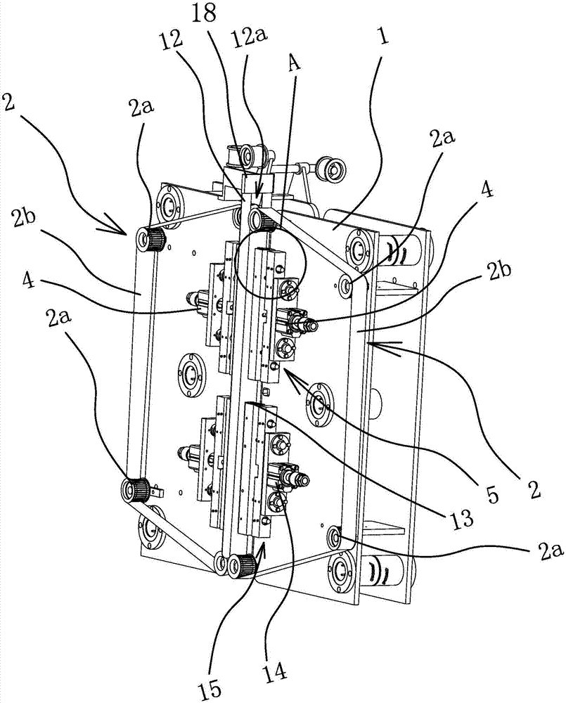
[0043] Such as Figure 1-12 As shown, the heat-sealing mechanism of the film heat-synthesizing device includes a mounting base 1, two guide rulers 12, two sets of driving rollers 2 that are arranged oppositely and are composed of several driving rollers 2, two oppositely arranged Heat-sealing cutter head 3 and two cooling cutter heads 13 which are elongated and oppositely arranged.

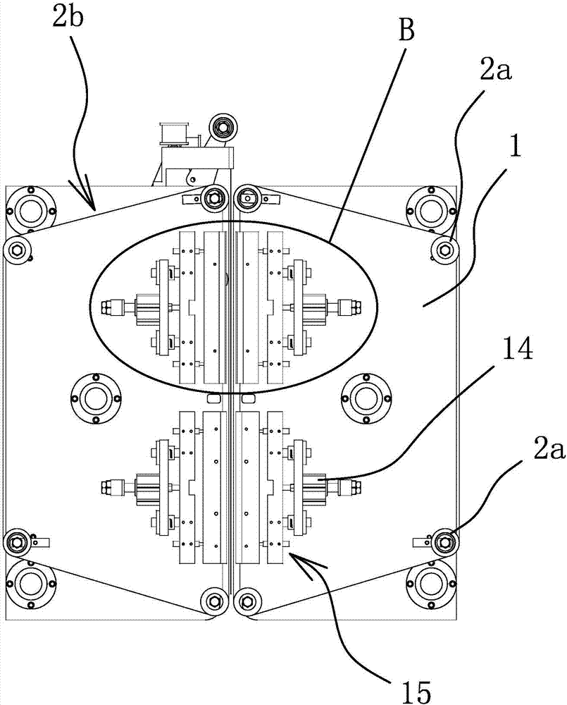
[0044]Two cooling cutter heads 13 and two heat-sealing cutter heads 3 are arranged side by side, and each group of driving rollers 2 includes four driving rollers 2a, and the four driving rollers 2a are arranged in an isosceles trapezoidal shape and are all rotatably connected to the mounting base 1. The driving rollers 2a in the driving roller group 2 are connected by a driving belt 2b made of a high-temperature-resistant heat-conducting material, and the driving belts 2b located at the bottom edge of the isosceles trapezoid on the two groups of driving roller groups 2 are parallel to each other ...

Embodiment 2

[0050] The structure of this embodiment is basically the same as that of Embodiment 1, the difference is: Figure 13 As shown, the adjustment assembly one 5 includes a slide block 5d and a slide rail 5c, the drive source one 4 is a cylinder, the cylinder body of the cylinder is fixed on the slide block 5d, the heat sealing cutter head 3 is fixed on the cutter head seat 7, and the piston rod of the cylinder It is connected with the cutter head seat 7, the slide rail 5c is fixed on the mounting base 1, the slide block 5d is slidably connected on the slide rail 5c, and there is also a set between the slide block 5d and the slide rail 5c that can position the slide block 5d on the slide rail 5c. Positioning piece two on the The piston rod of the air cylinder is directly connected with the cutter head holder 7 of the fixed heat sealing cutter head 3. Initially, the distance between the cylinder and the driving belt 2b can be adjusted by adjusting the position of the slide block 5d ...

Embodiment 3

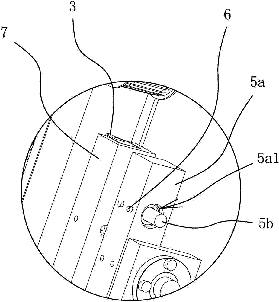
[0052] The structure of this embodiment is basically the same as that of Embodiment 1, the difference is: Figure 15 As shown, the heat-sealed cutter head 3 is cylindrical, and the heat-sealed cutter head 3 is rotatably connected to the cutter head seat 7. There are two adjusting rods 5b which are fixedly connected to the two ends of the cutter head seat 7 respectively. The adjustment block 5a and the cutter head The seats 7 are arranged side by side, both ends of the adjustment block 5a are provided with adjustment holes 5a1, and the adjustment rods 5b slide through the corresponding adjustment holes 5a1 respectively.


PUM


Abstract

The invention provides a heat sealing mechanism of a band and film heat sealing molding device and belongs to the technical field of machinery, aiming at solving the problem that the heat sealing effect on a thin film and a film pressing band of an existing heat sealing mechanism is poor. The heat sealing mechanism of the band and film heat sealing molding device comprises a mounting base, two groups of driving roller sets and two heat sealing tool bits; each driving roller in each group of driving roller set is rotatably connected onto the mounting base and is connected through a driving belt made of a high-temperature-resisting heat-conducting material; the driving belts on the two groups of driving roller sets penetrate through the two heat sealing tool bits; each heat sealing tool bit is connected with a driving source I; each heat sealing tool bit is further connected with an adjusting assembly I; after adjustment, the driving sources I can drive the heat sealing tool bits to get close to the corresponding driving belts or form a gap with the corresponding driving belts. By adopting the heat sealing mechanism provided by the invention, the thin film and the film pressing band can be enabled to keep a straight state and are fitted relatively well; the heat sealing between an ultra-wide type greenhouse thin film and the film pressing band can be realized and the heat sealing effect is improved.

Description

technical field [0001] The invention belongs to the technical field of machinery, and relates to a heat-sealing mechanism of a heat-synthesizing device with a film. Background technique [0002] Greenhouse is a frame-covered structure with excellent thermal insulation performance. It is a very important facility in the process of modern agricultural production and has been widely used in agricultural production in most areas of our country. The existing greenhouses all include a skeleton and a suspended cable-membrane structure. The suspended cable-membrane structure is a composite of plastic film and pressure-bearing cables. The film is fixed by heat sealing, and because the pressure-bearing cable is fixed between the plastic film and the plastic film belt, it is easy to slip between the pressure-bearing cable and the plastic film and the plastic film belt. Therefore, in order to facilitate farming in greenhouses, large-span greenhouses are required To improve the cost req...

Claims


Application Information

Patent Timeline
IPC IPC(8): B32B37/06B32B37/08B32B37/10B32B39/00
CPCB32B37/06B32B37/08B32B37/10B32B39/00
Inventor 甘汉南梅未
Owner BOEN SOLAR TECH
Why Eureka
Try Eureka