Automatic lifting and conveying mechanism for PCB distribution conveying box

An automatic lifting and conveying mechanism technology, applied in the direction of conveyors, conveyor objects, transportation and packaging, etc., can solve the problems of high handling frame, troublesome handling, troublesome handling, etc., and achieve high degree of automation, high efficiency and good effect Effect

Active Publication Date: 2017-06-20
龙南骏亚精密电路有限公司
View PDF8 Cites 3 Cited by
  • Summary
  • Abstract
  • Description
  • Claims
  • Application Information

AI Technical Summary

Problems solved by technology

[0002] The existing PCB sub-boards are placed in the transport box after processing, and then manually transported to the subsequent transport rack for subsequent pa

Method used


Image

  • Automatic lifting and conveying mechanism for PCB distribution conveying box
  • Automatic lifting and conveying mechanism for PCB distribution conveying box
  • Automatic lifting and conveying mechanism for PCB distribution conveying box

Examples


Embodiment Construction

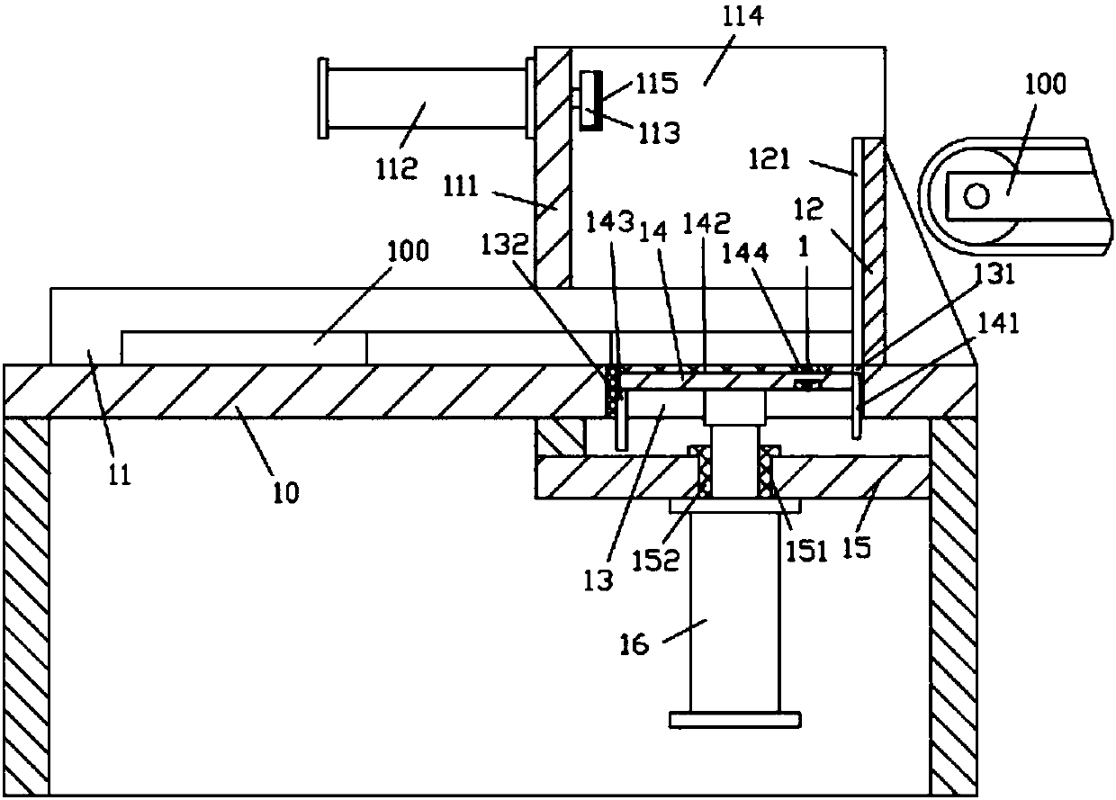
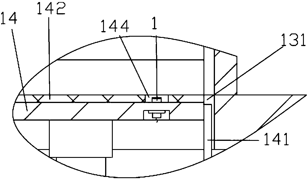
[0017] Examples, see e.g. Figure 1 to Figure 2 As shown, a kind of PCB sub-board conveying box automatic lifting conveying mechanism comprises a lifting frame 10, the front and rear sides of the top plate of the lifting frame 10 are fixed with running guide plates 11, and the right end top surface of the top plate of the lifting frame 10 A vertical support plate 12 is fixed, the left side wall of the vertical support plate 12 has a vertical guide groove 121, and the top plate of the lifting frame 10 on the left side of the vertical support plate 12 has a vertical lifting channel 13, The lifting plate 14 is inserted and sleeved in the vertical lifting channel 13, the bottom of the top plate of the lifting frame 10 is provided with a lower support plate 15, the bottom surface of the lower support plate 15 is fixed with a lifting cylinder 16, and the push rod of the lifting cylinder 16 passes through The guide through hole 151 provided on the lower support plate 15 is fixed in t...


PUM


Abstract

The invention discloses an automatic lifting and conveying mechanism for a PCB distribution conveying box. The automatic lifting and conveying mechanism comprises a lifting machine frame. Running guide plates are fixed to the front side and the rear side of a top plate of the lifting machine frame, a vertical support plate is fixed to the top surface of the right end of the top plate of the lifting machine frame, and a vertical guide groove is formed in the left wall of the vertical support plate. A vertical lifting through groove is formed in the portion, located on the left side of the vertical support plate, of the top plate of the lifting machine frame, and a lifting plate is inserted in the vertical lifting through groove in a sleeved mode. A lower support plate is arranged below the top plate of the lifting machine frame, a lifting cylinder is fixed to the bottom surface of the lower support plate, and a push rod of the lifting cylinder penetrates through a guide through hole formed in the lower support plate and is fixed to the middle portion of the bottom surface of the lifting plate. Main support plates are fixed to the top surfaces of the two running guide plates on the left of the vertical lifting through groove, and push cylinders are fixed to the left walls of the upper portions of the main support plates. The automatic lifting and conveying mechanism for the PCB distribution conveying box is capable of lifting the conveying box of a PCB distribution device automatically and pushing out the conveying box without manual transferring, high in efficiency and high in automation degree.

Description

Technical field: [0001] The invention relates to the technical field of circuit board manufacturing and processing, and more specifically relates to an automatic lifting and conveying mechanism for a PCB sub-board conveying box. Background technique: [0002] The existing PCB sub-boards are placed in the transport box after processing, and then manually transported to the subsequent transport rack for subsequent packaging and other processes. This transport rack is generally relatively high, and the handling is troublesome, and it is very cumbersome and automated. Not to a high degree. Invention content: [0003] The purpose of the present invention is to overcome the deficiencies of the prior art and provide an automatic lifting and conveying mechanism for the PCB sub-board delivery box, which can automatically lift the delivery box where the PCB sub-board is placed, and push it out without manual handling, and its efficiency is high. The effect is good and the degree of...

Claims


Application Information

Patent Timeline
IPC IPC(8): B65G47/57
CPCB65G47/57B65G2201/025
Inventor 王松
Owner 龙南骏亚精密电路有限公司
Why Eureka
Try Eureka