
Automatic clamping device

An automatic, one-size-fits-all technology, applied in transportation and packaging, cleaning methods using tools, conveyors, etc., can solve the problems of endangering personal safety, slow cleaning speed, long storage time, etc., to ensure physical safety and improve work efficiency , Low maintenance cost effect

Inactive Publication Date: 2017-06-20
郑飞
View PDF7 Cites 11 Cited by
  • Summary
  • Abstract
  • Description
  • Claims
  • Application Information

AI Technical Summary

Problems solved by technology

[0002] With the development of society and the improvement of people's living standards, when building and decorating houses, the quality requirements for various panels are relatively high. After the panels are cut and painted, they are left for too long, and they are full of dust when they are shipped, which affects their appearance. Some enterprises clean manually, but the artificial cleaning speed is slow, it is inconvenient to overturn the large plates, and it is easy to slip during the overturning process, which has potential safety hazards and endangers personal safety. The existing cleaning devices have high maintenance costs and are not suitable for some medium-sized Small enterprises, in order to meet market demand, need better and more complete equipment when clamping plates. In order to solve such problems, an automatic clamping device is needed, which is very necessary

Method used


Image

  • Automatic clamping device
  • Automatic clamping device
  • Automatic clamping device

Examples


Embodiment Construction

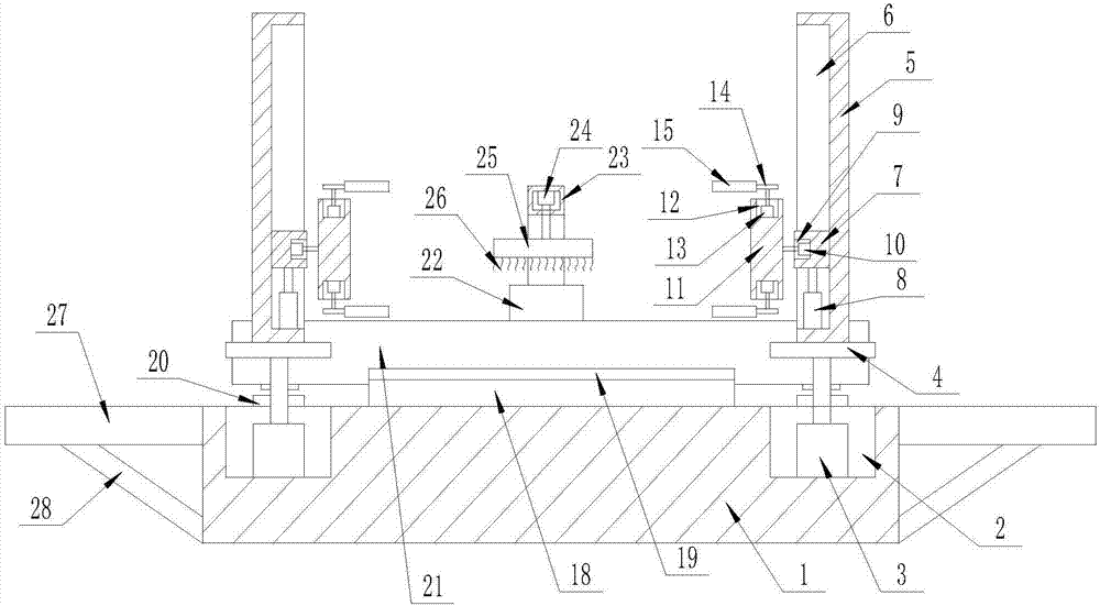
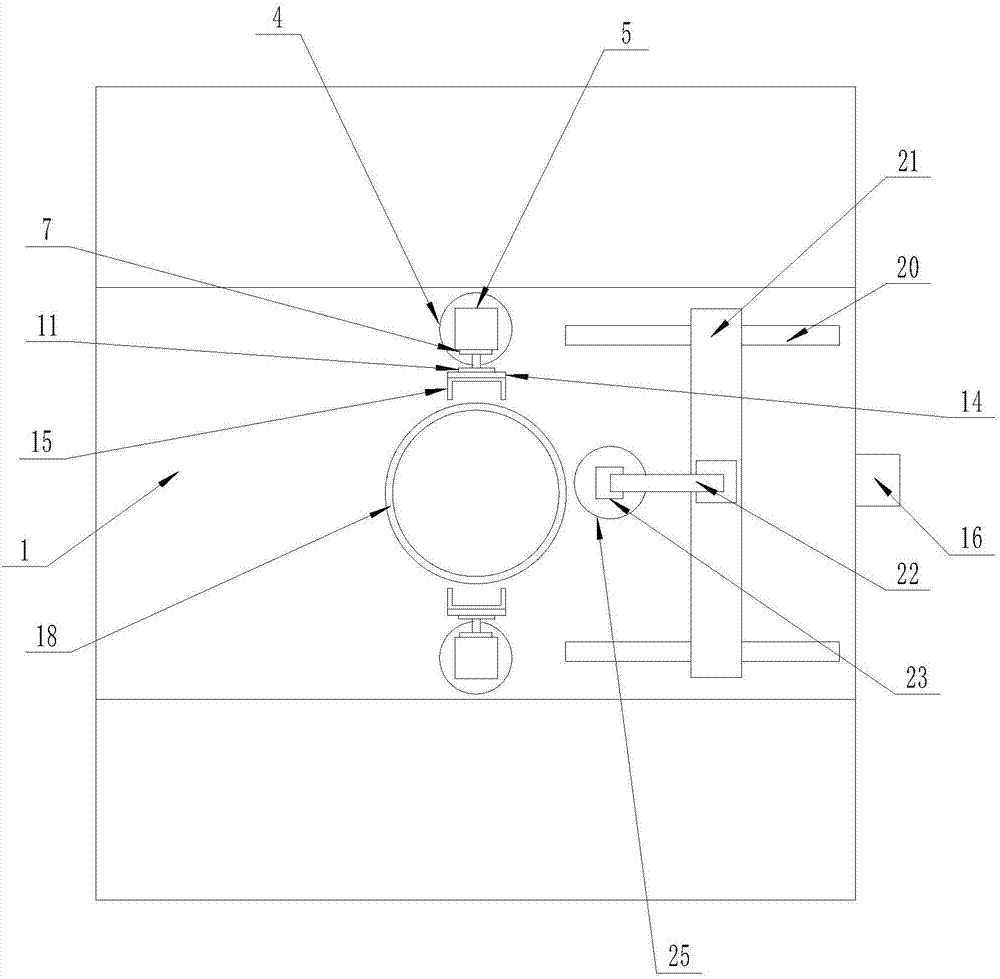
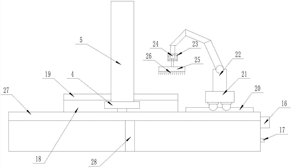
[0015] The present invention is specifically described below in conjunction with accompanying drawing, as Figure 1-3 As shown, an automatic clamping device includes a workbench (1), a group of No. 1 circular grooves (2) are processed at the center of the upper surface of the workbench (1), and each No. 1 circular groove The slots (2) are provided with No. 1 miniature rotating motors (3) with their rotating ends upward, and each No. 1 miniature rotating motor (3) is provided with a round groove (2) at the rotating end of each No. 1 miniature rotating motor (3). Matching pallets (4), each of the pallets (4) is provided with a support rod (5), and each of the support rods (5) is processed with a No. 1 slideway (6), the All be provided with slide block (7) in each No. 1 slideway (6), all be provided with the No. 1 electric push rod (8) that telescopic end upwards in described each No. 1 slideway (6), described each The telescopic ends of No. 1 electric push rods (8) are fixedly ...


PUM


Abstract

The invention discloses an automatic clamping device. The automatic clamping device comprises a working table; a group of No.1 circular grooves are machined in the center of the upper surface of the working table; a No.1 miniature rotating motor with the upward rotating end is arranged in each No.1 circular groove; the rotating end of each No.1 miniature rotating motor is provided with a supporting plate matched with the No.1 circular groove; a supporting rod is arranged on each supporting plate; a controller is arranged on the surface of one side of the working table; a mains supply interface is arranged below the controller and is electrically connected with the controller; and the input end of the controller is electrically connected with the No.1 miniature rotating motors, No.1 electric push rods, No.2 electric push rods and linear motors. The clamping device has the beneficial effects as follows: the device is simple to operate, automatic clamping, turning and cleaning are realized, plates are clean during delivery, the labor is liberated, the physical safety of workers is guaranteed, the working efficiency is improved, and the device is convenient and practical.

Description

technical field [0001] The invention relates to the field of automatic clamping of plates, in particular to an automatic clamping device. Background technique [0002] With the development of society and the improvement of people's living standards, when building and decorating houses, the quality requirements for various panels are relatively high. After the panels are cut and painted, they are left for too long, and they are full of dust when they are shipped, which affects their appearance. Some enterprises clean manually, but the artificial cleaning speed is slow, it is inconvenient to overturn the large plates, and it is easy to slip during the overturning process, which has potential safety hazards and endangers personal safety. The existing cleaning devices have high maintenance costs and are not suitable for some medium-sized Small enterprises, in order to meet market demand, need better and more complete equipment when clamping plates. In order to solve such problem...

Claims


Application Information

Patent Timeline
Patent Type & Authority Applications(China)
IPC IPC(8): B65G47/90B08B1/04B08B13/00
CPCB65G47/902B08B13/00B65G2201/022B08B1/12B08B1/32
Inventor 郑飞
Owner 郑飞
Learn More