Soil nail grouting head device and construction method thereof

A grouting head and soil nailing technology, which is applied in the engineering field, can solve problems such as the inability to accurately judge whether the grout is filled, the inability to completely fill the soil nail hole, and the grout overflowing the soil nail hole, so as to ensure the thickness, avoid the grout overflow, The effect of low grouting cost

Active Publication Date: 2017-06-20
THE FIRST COMPARY OF CHINA EIGHTH ENG BUREAU LTD
View PDF11 Cites 1 Cited by
  • Summary
  • Abstract
  • Description
  • Claims
  • Application Information

AI Technical Summary

Problems solved by technology

Compared with the pressure grouting method, the gravity grouting method has the advantages of simple grouting operation and low grouting cost; however, the gravity grouting method usually has the following problems: 1. The grout cannot completely fill the entire soil nail only by its own gravity. After grouting, the grouting often needs to be replenished several times. During the grouting and grouting, the grout often overflows the soil nail hole, causing the grout to drip and affect the construction quality; 2. It is impossible to accurately judge whether the grouting Full

Method used


Image

  • Soil nail grouting head device and construction method thereof
  • Soil nail grouting head device and construction method thereof
  • Soil nail grouting head device and construction method thereof

Examples


Embodiment 1

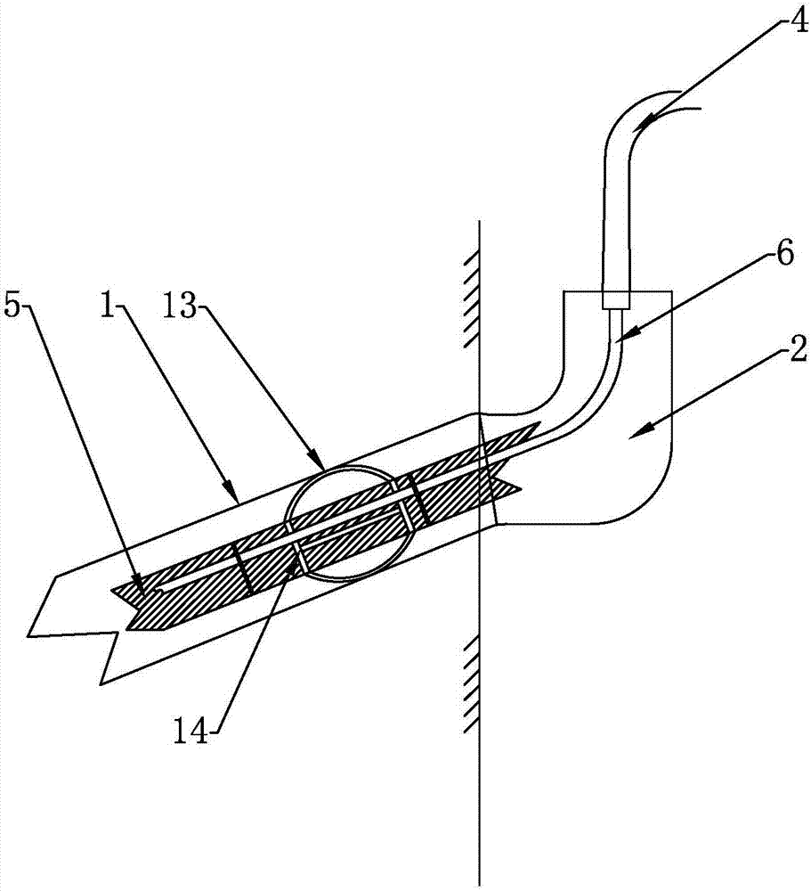
[0038] Such as figure 1 As shown, a soil nailing grouting head device includes a soil nailing steel bar and a steel sleeve 1 sleeved on the outside of the soil nailing steel bar. The centering bracket is fixed, and the outside of the centering bracket is fitted to the inner wall of the steel sleeve 1; a polyethylene pipe 6 is arranged outside the soil nail hole rod body 5, and the polyethylene pipe 6 is connected to the soil nail along the length direction of the soil nail hole rod body 5. The hole rod body 5 is arranged in parallel, and the polyethylene pipe 6 is bound to the soil nail hole rod body 5; an L-shaped grout stabilization pipe is connected to the end of the steel sleeve 1 close to the outside of the wall; the outlet of the external grouting hose 4 passes through the L-shaped The slurry stabilizing pipe links to each other with polyethylene pipe 6 inlets.

[0039] The L-shaped slurry-stabilizing pipe is an L-shaped PVC slurry-stabilizing pipe 2 .

[0040] The cen...

Embodiment 2

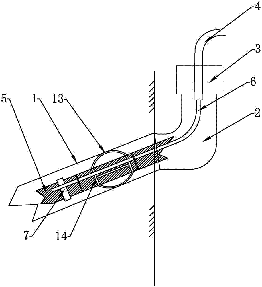
[0052] Such as figure 2 As shown, the soil nailing grouting head device includes a soil nailing steel bar and a steel sleeve 1 sleeved on the outside of the soil nailing steel bar, and the soil nailing steel bar includes a soil nailing hole rod body 5, which is clamped on the outside of the soil nailing hole rod body 5 Centering bracket, the outer side of the centering bracket is fitted to the inner side wall of the steel sleeve 1; a polyethylene pipe 6 is arranged on the outside of the soil nail hole rod body 5, and the polyethylene pipe 6 is connected to the soil nail hole along the length direction of the soil nail hole rod body 5 The rod body 5 is arranged in parallel, and the polyethylene pipe 6 is bound to the soil nail hole rod body 5; an L-shaped grout stabilization pipe is connected to the end of the steel sleeve 1 close to the outside of the wall; the outlet of the external grouting hose 4 passes through the L-shaped stabilizer The slurry pipe is connected with the ...

Embodiment 3

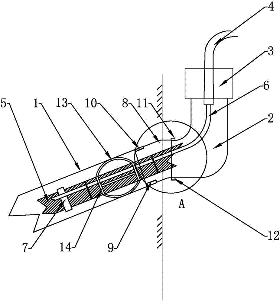
[0070] Such as Figure 3-6 As shown, the soil nailing grouting head device includes a soil nailing steel bar and a steel sleeve 1 sleeved on the outside of the soil nailing steel bar, and the soil nailing steel bar includes a soil nailing hole rod body 5, which is clamped on the outside of the soil nailing hole rod body 5 Centering bracket, the outer side of the centering bracket is fitted to the inner side wall of the steel sleeve 1; a polyethylene pipe 6 is arranged on the outside of the soil nail hole rod body 5, and the polyethylene pipe 6 is connected to the soil nail hole along the length direction of the soil nail hole rod body 5 The rod body 5 is arranged in parallel, and the polyethylene pipe 6 is bound to the soil nail hole rod body 5; an L-shaped grout stabilization pipe is connected to the end of the steel sleeve 1 close to the outside of the wall; the outlet of the external grouting hose 4 passes through the L-shaped stabilizer The slurry pipe is connected with th...


PUM


Abstract

The invention relates to the technical field of engineering, and in particular relates to a soil nail grouting head device and a construction method thereof. The soil nail grouting head device comprises a soil nail steel bar, and a steel sleeve which sleeves the outer side of the soil nail steel bar, wherein the soil nail steel bar comprises a soil nail hole rod body; a centering bracket is fixedly clamped at the outside of the soil nail hole rod body; a polyethylene pipe is arranged at the outer side of the soil nail hole rod body; an L-shaped slurry stabilizing pipe is connected to the outside of the steel sleeve; a grouting hose is connected with the polyethylene pipe. The construction method of the soil nail grouting head device comprises the steps of preparing for construction, mounting the steel sleeve, drilling a hole and cleaning the hole, mounting the soil nail steel bar, mounting the slurry stabilizing pipe, grouting at low pressure, and supplementing the slurry in a manner of grouting under gravitational force. According to the soil nail grouting head device and the construction method thereof, the advantages of grouting through a low-pressure grouting method and supplementing the slurry in a manner of grouting under gravitational force are combined, so that the circumstances that slurry cannot be uniformly grouted in the soil nail hole during being grouted and the slurry overflows when the soil nail hole is nearly fully filled with the slurry can be avoided; meanwhile, the supplemented slurry level can be conveniently observed, and whether the soil nail hole is full of the slurry can be determined; the soil nail grouting head device has the advantages of being simple to operate, and low in grouting cost; and the grouting quality is ensured.

Description

[0001] (1) Technical field [0002] The invention and the field of engineering technology, in particular, relate to a soil nailing grouting head device and a construction method thereof. [0003] (2) Background technology [0004] At present, in the walls of engineering buildings, the wall surface containing the gravel filter layer has the disadvantages of being difficult to drill and easy to collapse, which brings difficulties to the drilling construction before the steel pipe soil nailing grouting. Therefore, in the construction process, usually use Steel sleeves are used to protect the walls from collapsing. Steel pipe soil nailing grouting methods include gravity grouting method and pressure grouting method, pressure grouting method is divided into low pressure (0.4-0.6MPa) grouting method, high pressure (1-2MPa) grouting method, low pressure and high pressure combined grouting method law etc. The traditional low-pressure grouting method is to insert the grouting hose int...

Claims


Application Information

Patent Timeline
Patent Type & Authority Applications(China)
IPC IPC(8): E02D15/04
CPCE02D15/04
Inventor 胡杰杨海龙董彪向国华李军郭凤刚袁成太
Owner THE FIRST COMPARY OF CHINA EIGHTH ENG BUREAU LTD
Why Eureka
Try Eureka