Pile centering method and pile centering device for cast-in-situ piles during construction

A technology of cast-in-place piles and pile cores, which is applied in the direction of foundation structure engineering, sheet pile wall, foundation structure test, etc., can solve problems such as large errors, save manpower, improve engineering construction quality, and simple operation.

Active Publication Date: 2019-01-22
CHINA CONSTR EIGHT ENG DIV CORP LTD
View PDF6 Cites 0 Cited by
  • Summary
  • Abstract
  • Description
  • Claims
  • Application Information

AI Technical Summary

Problems solved by technology

[0004] In order to overcome the defects existing in the prior art, a pile core centering method and a cast-in-situ pile centering device during the construction of cast-in-situ piles are provided to solve the problem of positioning the positioned pile cores during the construction of cast-in-place piles. When rechecking or aligning, the traditional centering method only depends on the problem of large error of naked eye observation

Method used


Image

  • Pile centering method and pile centering device for cast-in-situ piles during construction
  • Pile centering method and pile centering device for cast-in-situ piles during construction
  • Pile centering method and pile centering device for cast-in-situ piles during construction

Examples


no. 1 example

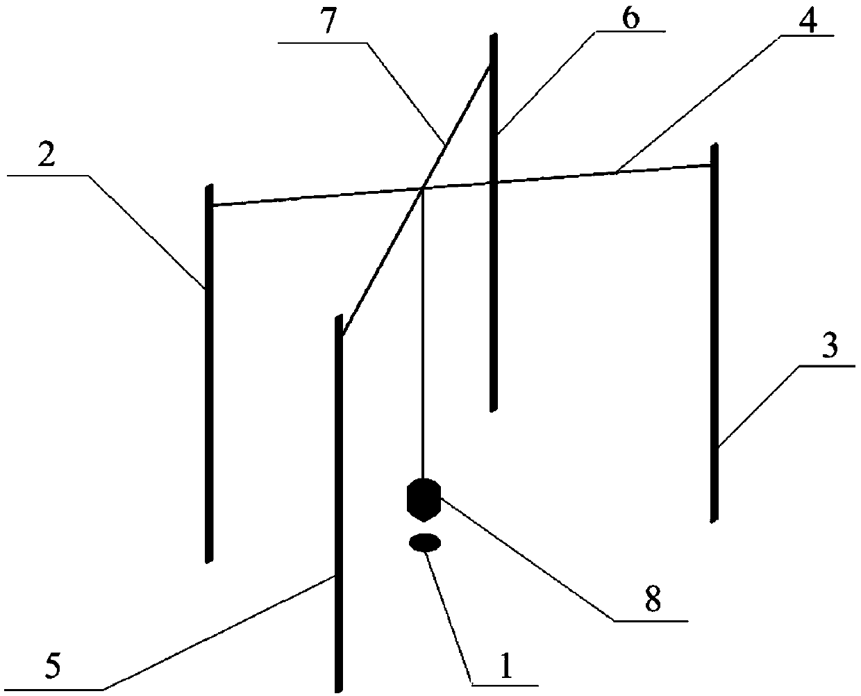
[0036] figure 1 It is the use state diagram of the cast-in-place pile centering device of the present invention, Figure 2 to Figure 7 It is a construction schematic diagram of the pile core centering method during the construction of the cast-in-place pile of the present invention.

[0037] see Figure 1 to Figure 7 , the present invention provides a cast-in-place pile core centering device including a first fixed rod 2, a second fixed rod 3, a first pair of pull wires 4, a third fixed rod 5, a fourth fixed rod 6, and a second pair of pull wires 7 and positioning tool 8.

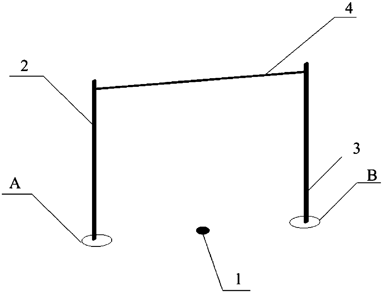
[0038] The first fixed rod 2 is vertically inserted at the first fixed point A, the second fixed rod 3 is vertically inserted at the second fixed point B, and a first pair of the first fixed rod 2 and the second fixed rod 3 are connected. The stay wire 4, the first fixing point A and the second fixing point B are located on opposite sides of the pile core 1 of the cast-in-place pile.

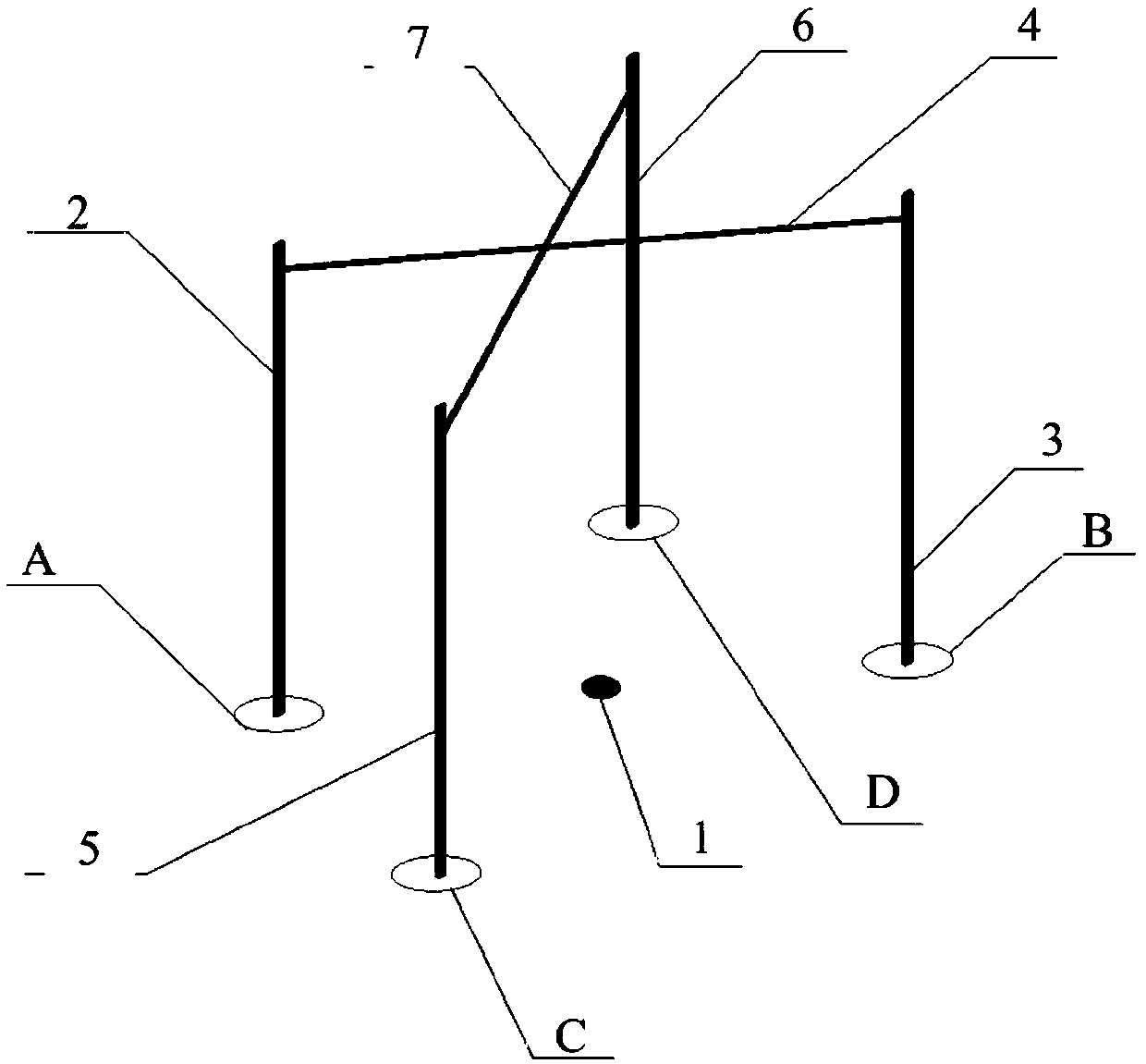
[0039] The third ...

no. 2 example

[0065] The invention provides a cast-in-place pile core centering device comprising a first fixed rod, a second fixed rod, a first pair of pulling wires, a third fixing rod, a fourth fixing rod, a second pair of pulling wires and a positioning tool.

[0066] The first fixed rod is vertically inserted at the first fixed point, the second fixed rod is vertically inserted at the second fixed point, and a first pair of pull wires are connected between the first fixed rod and the second fixed rod, and the first fixed point and the second fixing points are located on opposite sides of the core of the cast-in-place pile.

[0067] The third fixed rod is vertically inserted at the third fixed point, the fourth fixed rod is vertically inserted at the fourth fixed point, a second pair of pull wires are connected between the third fixed rod and the fourth fixed rod, and the third fixed point and the second fixing points are located on opposite sides of the pile core, and the first pair of...


PUM


Abstract

The invention provides a pile center centering method and a cast-in-place pile center centering device for the cast-in-place pile construction process. Four proper positions are found near the pile center of a cast-in-place pile, fixing rods are vertically arranged between every two opposite points and connected through opposite-pulling lines, and the two opposite-pulling lines are made to intersect above the pile center of the cast-in-place pile; and every two adjacent fixing rods are finely adjusted correspondingly, the two opposite-pulling lines are made to intersect at an intersecting point which is located over the pile center through a positioning tool, and then the first opposite-pulling line and the second opposite-pulling line are removed. During later cast-in-place pile construction, the first opposite-pulling line and the second opposite-pulling line can be arranged between the fixing rods to rapidly center the pile center of the cast-in-place pile. By means of the pile center centering method and the cast-in-place pile center centering device for the cast-in-place pile construction process, the problem that during pile center centering in the cast-in-place pile construction process, errors are large due to the fact that naked-eye observation is only adopted in traditional centering methods is solved.

Description

technical field [0001] The invention relates to the field of building construction, in particular to a pile core centering method and a cast-in-place pile centering device during the construction of a cast-in-place pile. Background technique [0002] Cast-in-place pile is a foundation pile widely used in industrial plants, civil buildings, high-speed railways, bridges and other fields. Before the construction of cast-in-place piles, technicians usually use instruments and equipment to accurately locate and place the core of the pile. During the construction of cast-in-place piles, such as: construction of the pile foundation, positioning of the pile driver, positioning of the drill bit of the pile driver, positioning of the pile foundation casing, and positioning of the pile foundation reinforcement cage, the positioned pile cores need to be positioned and reviewed many times. Because the construction site environment of cast-in-place piles is poor, the foundation pit is un...

Claims


Application Information

Patent Timeline
Patent Type & Authority Patents(China)
IPC IPC(8): E02D33/00E02D5/34
CPCE02D5/34E02D33/00
Inventor 焦德贵崔华久潘立吴小鹏韩云鹏艾迪飞陈仲明
Owner CHINA CONSTR EIGHT ENG DIV CORP LTD
Why Eureka
Try Eureka