
Laser radar scanning method and laser radar scanning device

A technology of laser radar and scanning beams, which is applied in the field of safety, can solve the problems of train or vehicle safety hazards, whether there are dangerous objects that cannot be sensed, and achieve the effect of eliminating blind spots in detection

Active Publication Date: 2017-06-20
BEIJING JIAXUN FEIHONG ELECTRIC CO LTD
View PDF5 Cites 13 Cited by
  • Summary
  • Abstract
  • Description
  • Claims
  • Application Information

AI Technical Summary

Problems solved by technology

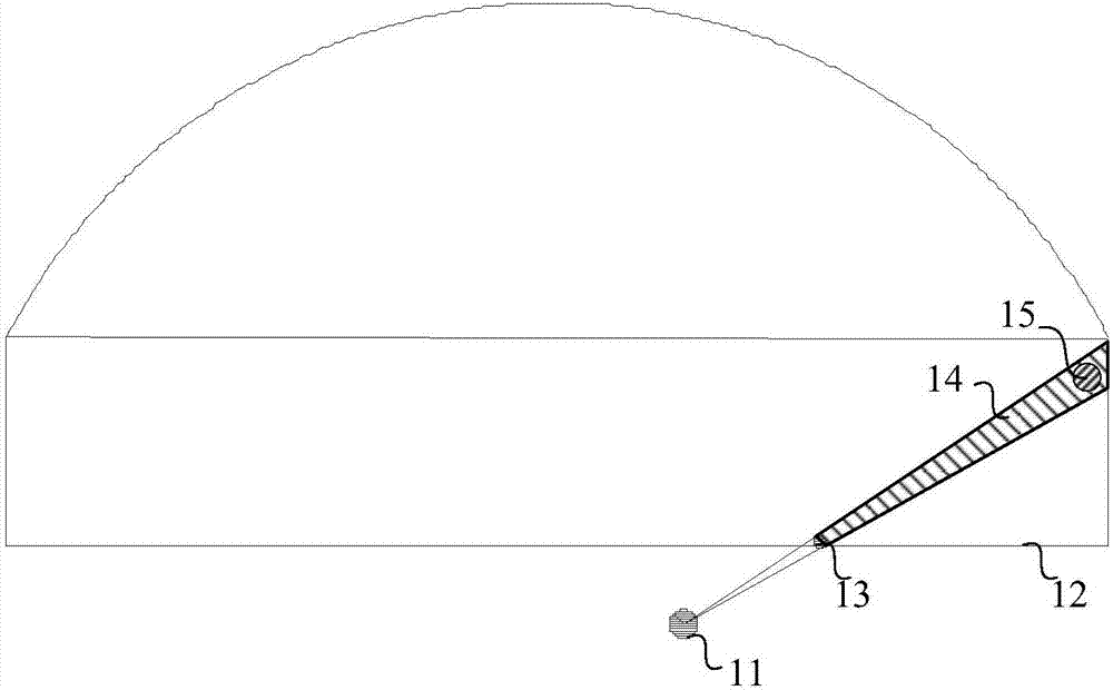
[0004] In practical applications, the scanning beam is easily blocked by obstacles close to the lidar position, and a detection shadow area is formed along the scanning beam in a large area farther away from the lidar. The lidar system cannot perceive whether there are dangerous objects in the shadow area.
If there is a large dangerous obstacle in the scanning shadow area, it will cause a major safety hazard to the moving train or vehicle

Method used


Image

  • Laser radar scanning method and laser radar scanning device
  • Laser radar scanning method and laser radar scanning device
  • Laser radar scanning method and laser radar scanning device

Examples


Embodiment Construction

[0025] The present invention will be further described in detail below with reference to the drawings and embodiments. It can be understood that the specific embodiments described here are only used to explain the present invention, but not to limit the present invention. In addition, it should be noted that, for ease of description, the drawings only show a part but not all of the content related to the present invention.

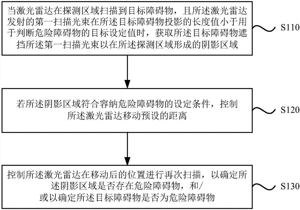
[0026] Figure 1A This is a flow chart of lidar scanning provided by an embodiment of the present invention. This embodiment is applicable to various lidar scanning situations. This method can be executed by the lidar scanning device provided by the embodiment of the present invention. Implementation in software and / or hardware, the method includes:

[0027] S110. When the lidar scans the target obstacle in the detection area, and the length value of the first scanning beam emitted by the lidar on the target obstacle is less than the target setting value for ju...


PUM


Abstract

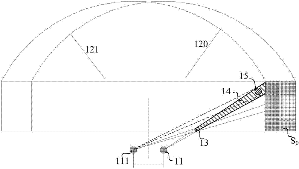
The invention discloses a laser radar scanning method and a laser radar scanning device. The method comprises the following steps: when a laser radar scans a target obstacle in a detection area and the length value of the projection of a first scanning light beam emitted by the laser radar on the target obstacle is smaller than a target set value for judging dangerous obstacles, acquiring a shadow area which is formed in the detection area when the target obstacle blocks the first scanning light beam; if the shadow area meets set conditions for accommodating a dangerous obstacle, moving the laser radar by a preset distance; and making the laser radar carry out scanning again at the position to which the laser radar is moved in order to determine whether there is a dangerous obstacle in the shadow area and / or determine whether the target obstacle is a dangerous obstacle. According to the embodiments of the invention, whether there is a dangerous obstacle in a shadow area formed when an obstacle blocks a scanning light beam can be judged, blind spots for detection of special-shaped obstacles in a detection area can be eliminated, and whether a special-shaped obstacle is a dangerous obstacle can be judged.

Description

Technical field [0001] The present invention relates to the field of safety technology, in particular to a laser radar scanning method and device. Background technique [0002] Transportation plays an important role in the national economy, and transportation safety is a major issue related to the national economy and people's livelihood. At present, Chinese railway companies have begun to use lidar to scan and measure within the safety limits of railway traffic in order to find obstacles that exceed the safe range and avoid danger to high-speed trains. [0003] At present, this kind of line obstacle safety monitoring system collects echo distance, PTZ direction and angle information and relative position information of the sensor and the monitoring area, determines the position, movement speed and direction of obstacles through calculation, and analyzes the threat of obstacles to driving safety degree. [0004] In practical applications, the scanning beam is easily blocked by obst...

Claims


Application Information

Patent Timeline
Patent Type & Authority Applications(China)
IPC IPC(8): G01S17/93
CPCG01S17/93
Inventor 马剑吕志东
Owner BEIJING JIAXUN FEIHONG ELECTRIC CO LTD
Learn More