Emergency return landing speed command set design method

A speed command and design method technology, applied in the field of flight control, can solve the problems of small flight speed, long flight distance and time, and uncertain engine parking conditions in the air, and achieve the effect of flexible adjustment and saving flight time.

Active Publication Date: 2017-06-20
FLIGHT AUTOMATIC CONTROL RES INST
View PDF2 Cites 7 Cited by
  • Summary
  • Abstract
  • Description
  • Claims
  • Application Information

AI Technical Summary

Problems solved by technology

However, when it is applied to engineering practice, it lacks the consideration of the following three issues: 1) In the process of idling return, the engine must be started in the air, and gliding with the maximum lift-to-drag ratio may not be able to reach the speed condition of the engine idling; 2) If the maximum lift-to-drag ratio speed is used to descend, the flying speed should be relatively low within the flying speed range. C

Method used


Image

  • Emergency return landing speed command set design method
  • Emergency return landing speed command set design method
  • Emergency return landing speed command set design method

Examples


Embodiment

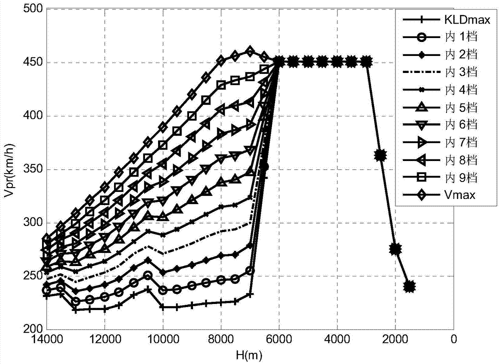
[0069] Taking a certain model as an example, given the conditions of the aircraft mass and the airport altitude of 1500m, and given the engine restart window as flying at a speed of 450km / h at an altitude of 3-6km, the main steps and results of designing a multi-speed instruction set are given:

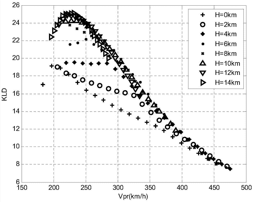
[0070] Step 1: Generate a parameter grid, calculate the air-slip performance and design multi-speed speed commands, and the lift-to-drag ratio of some grid points with the speed distribution curve is as follows: figure 1 shown.

[0071] 1) Take 100m as the altitude interval to form an altitude calculation sequence from the airport altitude to the maximum altitude; take the roll angle sequence of 0:10:30; query the flight envelope corresponding to the current quality, and calculate the speed range of each point in the altitude sequence And carry out 50 equal divisions to obtain the roll angle-height-velocity parameter grid; at each point of the parameter grid, calculate the angle of at...


PUM


Abstract

The invention belongs to a field of flight control technology and discloses an emergency return landing speed command set design method. The method includes (1), constructing a grid of mass, rolling angle, airport height, height and speed parameters, calculating an attack angle, an elevator, a lift-drag ratio, a track angle and a submerge rate of constant speed gliding of an aircraft, determining the maximal lift-drag ratio rate and the idle gliding maximal available speed changing along with mass, rolling angle, airport height and height, dividing a speed range between the maximal lift-drag ratio rate and the idle gliding maximal available speed into N+1 parts, adding the maximal lift-drag ratio rate and the idle gliding maximal available speed for creating a N+2 grade speed command set, wherein the content of each grade of the speed command set includes the attack angle, the elevator, the lift-drag ratio, the track angle and the submerge rate corresponding to the speed of said grade; (3) recording the N+2 grade speed command set by the aircraft, and selecting an appropriate speed command set grade for execution according to the mass, the airport height, the height, the speed and the distance between the aircraft and the airport when emergency aircraft return landing is required.

Description

technical field [0001] The invention belongs to the flight control technology, and in particular relates to an autonomous guidance and control technology for an aircraft without power to return to the field and land. Background technique [0002] When the aircraft has an engine shutdown failure in the air, the performance of the aircraft is degraded and it can only fly downhill. In order to ensure flight safety, it is necessary to control the speed of the aircraft and modify the flight trajectory to avoid stalling caused by excessive trajectory pull-up. At the same time, the lift-to-drag ratio of the aircraft glide can be adjusted to land the aircraft on the airport runway as much as possible. The literature "Design of Emergency Landing Control Law for Wheeled Take-off and Landing UAVs" provides a difficult analysis and solution to the problem of idling back and landing: 1) In the transitional flight phase, use the maximum lift-to-drag ratio speed to glide to maximize The f...

Claims


Application Information

Patent Timeline
IPC IPC(8): G05D1/10
CPCG05D1/101
Inventor 王霄婷王跃萍刘玮朱雪耀魏文领闻子侠
Owner FLIGHT AUTOMATIC CONTROL RES INST
Why Eureka
Try Eureka