Supercharge Your Innovation With Domain-Expert AI Agents!

Protective isolation device

A technology of protection isolation and guardrail, applied in the direction of fluid pressure actuating devices, servo motors, roads, etc., can solve the problems of inconvenient management, inflexible use, setting restrictions, etc., and achieve the effect of convenient control, simple structure and convenient installation.

Pending Publication Date: 2017-06-23
广西远望科技股份有限公司
View PDF6 Cites 1 Cited by
  • Summary
  • Abstract
  • Description
  • Claims
  • Application Information

AI Technical Summary

Problems solved by technology

[0003] 1. The fixed protective device is used, the setting is limited, and it becomes a fixed isolation after installation, which is inflexible in use and inconvenient in management;
[0004] 2. The personnel of the mobile protective device and the isolation area do not really form an isolation state, there are potential safety hazards, and it is easy to enter by mistake and cause a safety accident

Method used


Image

  • Protective isolation device
  • Protective isolation device
  • Protective isolation device

Examples


Embodiment 1

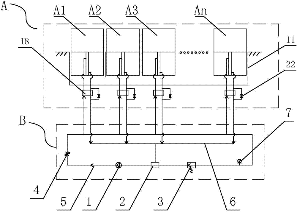
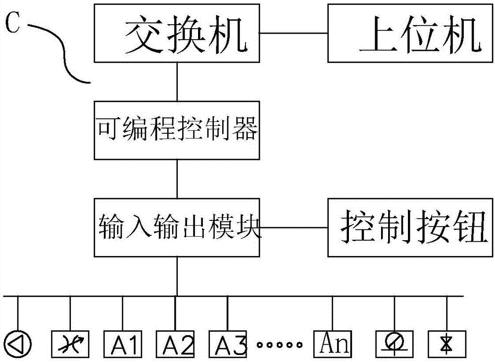
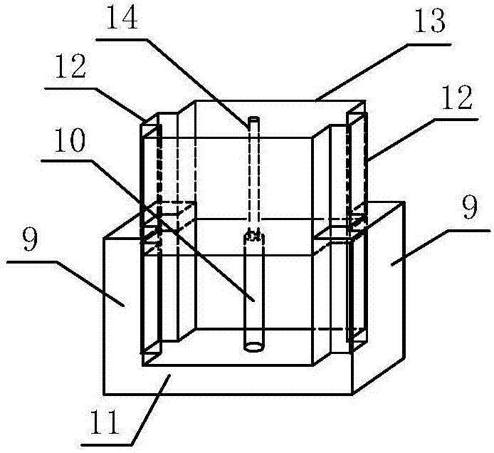
[0035] A protective isolation device, including a guardrail system A, a hydraulic system B and a control system C; the guardrail system is connected to the telescopic mechanism of the hydraulic system, and the hydraulic system is connected to the control system circuit and drives the telescopic mechanism under the control of the control system Lifting so as to drive the lifting of the guardrail system; the guardrail system includes 10 sets of guardrails arranged in sequence, and the n sets of guardrails are respectively connected with the n sets of telescopic mechanisms of the hydraulic system, and the n sets of guardrails have the same structure, including lifting bars 13, base 11 and the side plates 9 fixedly connected to the two sides of the base plate, the lifting rail is installed between the two side plates and is slidably matched with the two side plates, the lifting rail is a flat square frame with a downward opening, and its top surface is connected with the bottom plat...

Embodiment 2

[0041] A protective isolation device, the structure of which is basically the same as that of Embodiment 1, the difference is that: the two sides of the lifting rail are guide rails, and the matching side plates are provided with guide grooves, and the cross-sectional shape of the guide rails and guide grooves is square.

[0042] As a modification of the above embodiment, the cross-sectional shape of the guide rail and the guide groove can also be arc-shaped or triangular.

[0043] In the above embodiments, the number of guardrails installed can be increased or decreased according to actual needs. Generally, n is any integer between 1 and 100.

[0044] working principle

[0045]When the upper computer or the up button of the control button is activated, the hydraulic pump is started, the throttle valve is opened, and the hydraulic oil is distributed to the oil inlet pipe through the hydraulic pipe. Entering the lower part of the hydraulic cylinder, the hydraulic oil pushes th...


PUM


Abstract

A protective isolation device comprises a guardrail system, a hydraulic system and a control system. The guardrail system is connected with telescopic mechanisms of the hydraulic system, and the hydraulic system is in circuit connection with the control system and is controlled by the control system to drive falling and rising of the guardrail system; the guardrail system comprises n guardrails which are sequentially arranged and installed and connected with the n telescopic mechanisms of the hydraulic system, and the n guardrails have the same structure and each comprises a lifting fence, a bottom plate and two side plates fixed to the two sides of the bottom plate, wherein the lifting fence is installed between the two side plates and sliably matched with the side plates and is a flat square framework, the top face of the lifting fence is connected with the telescopic mechanism which is installed on the base plate and stretches into an inner cavity of the lifting fence, and the telescopic mechanism rises and falls to drive the lifting fence to rise or fall along the side plates. The device is simple in structure, convenient to install and manage, precise in control, safe and reliable; operation can be conducted according to a preset mode or be set manually on site, and the number of the guardrail system can be flexibly configured according to the site or management requirement.

Description

technical field [0001] The invention relates to a protection device, in particular to a hydraulic lifting protection isolation device for area isolation. Background technique [0002] At present, for the safety isolation and protection of specific areas, such as railways, highways and other driving areas, passenger platforms, or other areas that require safety isolation, the safety isolation devices used are either fixed protection devices or mobile protection that needs to be transported. device, the problem is: [0003] 1. The fixed protective device is used, the setting is limited, and it becomes a fixed isolation after installation, which is inflexible in use and inconvenient in management; [0004] 2. The personnel of the mobile protective device and the isolation area do not really form an isolation state, there are potential safety hazards, and it is easy to enter by mistake and cause a safety accident. Contents of the invention [0005] The technical problem to...

Claims


Application Information

Patent Timeline
IPC IPC(8): E01F13/04F15B11/08F15B13/04
CPCF15B11/08F15B13/0401E01F13/046
Inventor 许军
Owner 广西远望科技股份有限公司
Features
  • R&D
  • Intellectual Property
  • Life Sciences
  • Materials
  • Tech Scout
  • Unparalleled Data Quality
  • Higher Quality Content
  • 60% Fewer Hallucinations
Learn More