Clutch device

A clutch device and clutch technology, which is applied in the field of clutches, can solve the problems of limited friction between the shoe block and the follower, slow response speed of the shoe block and the follower, etc., to eliminate gaps, avoid excessive temperature rise, and improve service life. Improved effect

Inactive Publication Date: 2017-06-23
CHONGQING CHANGAN CLUTCH MFG
View PDF1 Cites 5 Cited by
  • Summary
  • Abstract
  • Description
  • Claims
  • Application Information

AI Technical Summary

Problems solved by technology

The problem with the existing centrifugal clutch is that the two ends of the two shoes are connected by springs, so that only two shoes can be arranged in the clutch, resulting in limited friction between the shoes and the follower
[0004] At the same time, the spring is used as the return device, resulting in a slow response when the shoe block and the follower are separated

Method used


Image

  • Clutch device
  • Clutch device

Examples


Embodiment 1

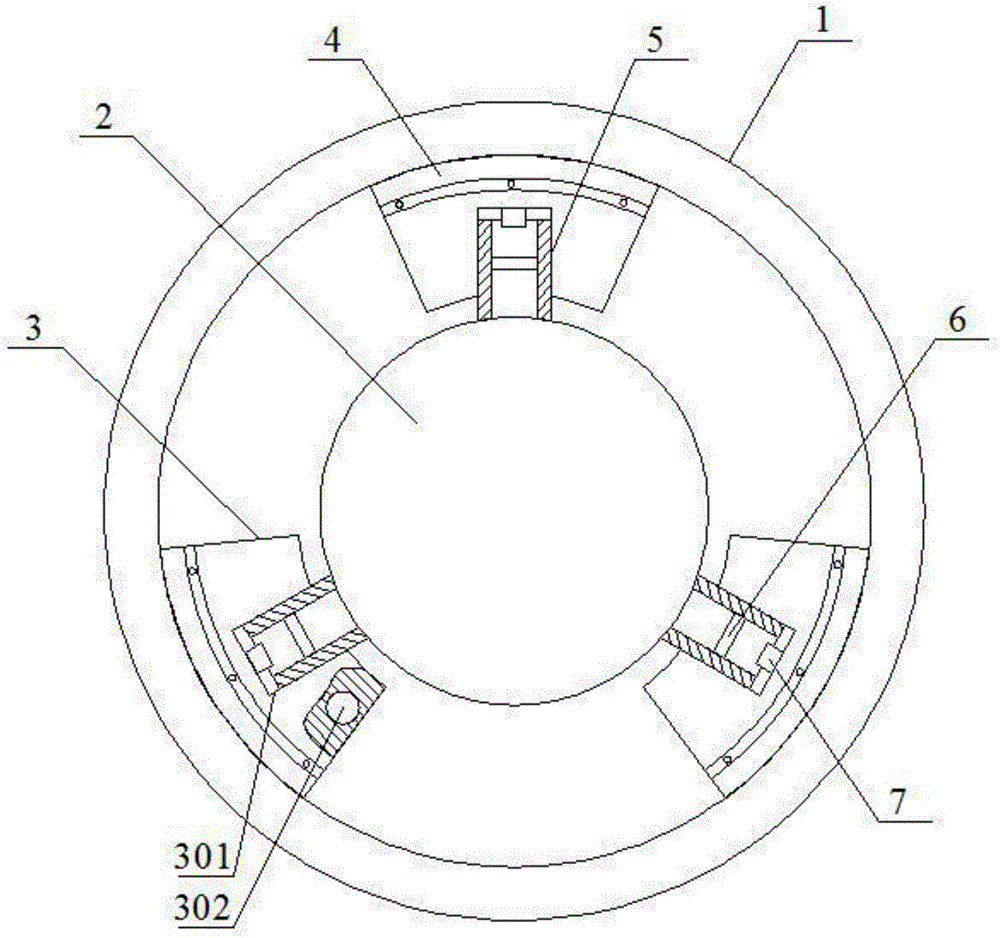
[0034] Such as figure 1 As shown, the clutch device includes a clutch casing 1, a runner 2, a shoe block 3, a friction plate 4, a guide cylinder 5, a first magnet 6 and a second magnet 7; the runner 2 is arranged in the clutch casing 1, and the runner 2 Coaxial with the clutch housing 1, the runner 2 is evenly provided with at least three guide cylinders 5 in the radial direction, the number of shoe blocks 3 is the same as that of the guide cylinders 5, and the shoe block 3 is provided with a guide hole 301, and the guide hole 301 and the guide cylinder 5 sliding fit, the first magnet 6 is set in the guide cylinder 5, the second magnet 7 is set in the bottom of the guide hole 301, the first magnet 6 and the second magnet 7 attract each other, and the friction plate 4 is fixed on the outer circle of the shoe 3 surface; the outer diameter of the friction plate 4 is the same as the inner diameter of the clutch housing 1; the shoe block 3 is provided with a housing cavity 302, and...

Embodiment 2

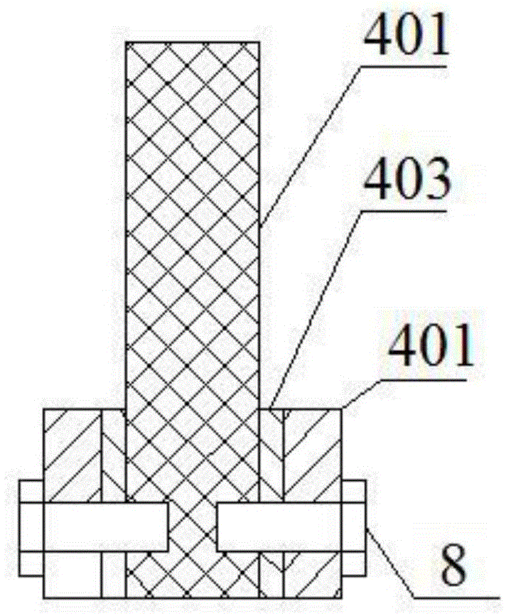
[0038] Such as figure 1 and figure 2 As shown, this embodiment is based on Embodiment 1. The friction plate 4 includes a connecting piece 401 fixed on the outer surface of the shoe block 3 and a friction part 402 fixed on the connecting piece 401. The friction part 402 The outer diameter of the friction part 402 is larger than the outer diameter of the connecting plate 401 , and the outer diameter of the friction part 402 is the same as the inner diameter of the clutch housing 1 .

[0039] During operation, the friction plate 4 is used for friction with the clutch housing 1, and the friction plate 4 is damaged quickly and needs to be replaced regularly. In order to facilitate the replacement of the friction plate 4, the friction plate 4 includes a connecting piece 401 fixed on the outer surface of the shoe block 3 and a friction part 402 fixed on the connecting piece 401, and the friction part 402 rubs against the clutch housing 1 during operation. After the friction force ...

Embodiment 3

[0041] Such as figure 1 and figure 2 As shown, this embodiment is based on Embodiment 2, and the friction part 402 is connected to the connecting piece 401 through bolts 8 .


PUM


Abstract

The invention discloses a clutch device. The clutch device comprises a clutch shell, a rotating wheel, shoe blocks, friction pieces, guide cylinders, first magnets and second magnets. The rotating wheel is arranged in the clutch shell. The rotating wheel and the clutch shell are arranged on the same axis. At least three guide cylinders are uniformly arranged on the rotating wheel in a radial direction. The number of the shoe blocks in the same as that of the guide cylinders. Guide holes are arranged in the shoe blocks and match the guide cylinders in a sliding manner. The first magnets are arranged in the guide cylinders. The second magnets are arranged in the bottoms of the guide holes. The first magnets attract to the second magnets. The friction pieces are fixed on outer cylindrical surfaces of the shoe blocks. The outer diameters of the friction pieces are the same as the inner diameter of the clutch shell. Accommodating cavities are formed in the shoe blocks and filled with water. The clutch device is not only capable of separating the shoe blocks from the clutch shell more flexibly but also preventing the temperature of the friction pieces from rising too fast.

Description

technical field [0001] The invention relates to a clutch. Background technique [0002] Centrifugal clutch transmits torque through friction, and its basic structure consists of three elements: driving part, centrifugal body and driven part. The centrifuge is slipped on the active part, and the prime mover drives the active part to rotate and accelerate to throw it out in the radial direction. When the driving part reaches the specified angular velocity, the thrown out centrifugal body is pressed against the inner wall of the driven part, and is forced into a motion state by friction force to transmit torque. [0003] Existing centrifugal clutches, such as the clutch disclosed in the invention patent application No. 201410498467, the centrifugal body includes two shoe blocks, the two ends of the two shoe blocks are connected by springs, and when the speed of the active part decreases, the pulling force of the springs Pull the shoe back to separate the shoe from the followe...

Claims


Application Information

Patent Timeline
Patent Type & Authority Applications(China)
IPC IPC(8): F16D43/18F16D69/02
CPCF16D43/18F16D69/02
Inventor 谢惠
Owner CHONGQING CHANGAN CLUTCH MFG
Why Eureka
Try Eureka