
A Broadband Composite Magnetic Sensor

A technology of magnetic sensor and fluxgate sensor, which is applied in the direction of measuring geometric arrangement of magnetic sensing elements, instruments, scientific instruments, etc., can solve the problems of high noise, high noise, low sensor sensitivity, etc., and overcome the high frequency noise , Improve the sensitivity, the effect of wide-band low-noise magnetic field measurement

Active Publication Date: 2019-07-05
JILIN UNIV
View PDF5 Cites 0 Cited by
  • Summary
  • Abstract
  • Description
  • Claims
  • Application Information

AI Technical Summary

Problems solved by technology

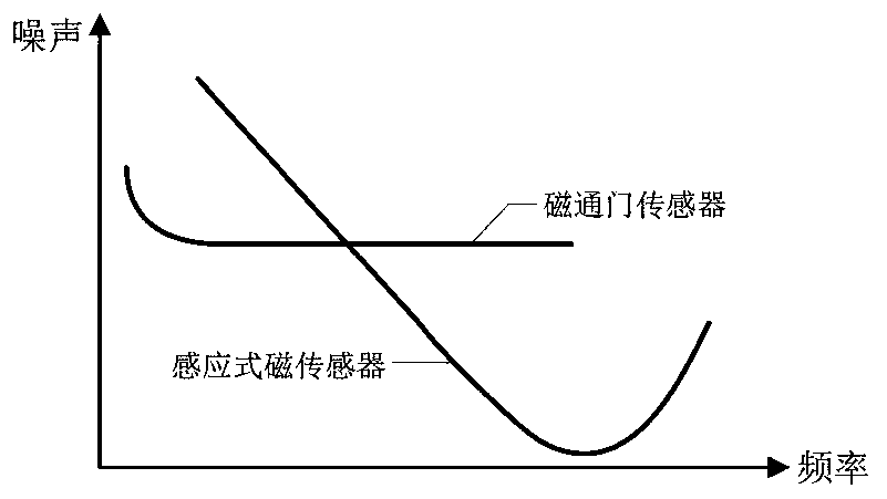
[0004] Inductive magnetic sensors and fluxgate sensors are widely used in magnetic field monitoring in different environments, but limited by their own working principles, inductive magnetic sensors can only measure alternating magnetic fields, and the lower the frequency, the greater their own noise; the fluxgate The sensor can measure the magnetic field in the DC-kHz range, but the noise is large in the high frequency band. The noise comparison between the inductive magnetic sensor and the fluxgate sensor is as follows: figure 1 shown
[0005] Aiming at the problem that a single inductive magnetic sensor or fluxgate sensor cannot realize full-band low-noise magnetic field measurement, CN102736113A proposes an ultra-wideband weak magnetic sensor suitable for DC-10kHz, using a cuboid high-permeability magnetic rod as an inductive magnetic field. The sensor core, and the sensitive element of the time difference fluxgate sensor is pasted on the surface. This composite magnetic sensor can realize broadband magnetic field measurement, but due to the influence of the high permeability magnetic rod on the fluxgate sensitive element, the magnetic field of this structure Pass door sensor has low sensitivity

Method used


Image

  • A Broadband Composite Magnetic Sensor
  • A Broadband Composite Magnetic Sensor
  • A Broadband Composite Magnetic Sensor

Examples


Embodiment 1

[0057] The broadband composite magnetic sensor is composed of an inductive magnetic sensor primary probe 1 and an inductive magnetic sensor secondary probe 2 installed at both ends of the shell 4 with a distance of 40mm, and the fluxgate sensor probe 3 is fixed on the inductive magnetic sensor primary probe 1 , The middle position of the inductive magnetic sensor secondary probe 2, the inductive magnetic sensor primary probe 1, the inductive magnetic sensor secondary probe 2 and the fluxgate sensor probe 3 are connected to the conditioning circuit 6 through a six-core shielded cable 5.

[0058] The primary probe 1 of the inductive magnetic sensor has the same structure as the secondary probe 2 of the inductive magnetic sensor.

[0059] The primary probe 1 of the inductive magnetic sensor and the secondary probe 2 of the inductive magnetic sensor are installed in the center of the skeleton 8 of the inductive magnetic sensor with the hollow core 7 of the inductive magnetic sensor...


PUM


Abstract

The invention relates to a broadband composite magnetic sensor. An inductive magnetic sensor primary probe and an inductive magnetic sensor secondary probe are installed at two ends. A fluxgate sensor probe is installed at the middle position of an inductive sensor hollow magnetic core. The inductive magnetic sensor primary probe, the inductive magnetic sensor secondary probe and the fluxgate sensor probe are fixed in a shell and are connected to a conditioning circuit through multi-core shielding cables. The broadband composite magnetic sensor has a high frequency working mode and a low frequency working mode, the fluxgate sensor probe is fixed to a composite magnetic sensor structure at the middle position of the inductive magnetic sensor primary probe and the inductive magnetic sensor secondary probe. Compared with a traditional single fluxgate sensor, the broadband composite magnetic sensor has the advantages that the sensitivity of a fluxgate sensor is improved, disadvantages that the high frequency noise of the single fluxgate sensor is high, the low frequency noise of a single inductive magnetic sensor is high, and a static magnetic field can not be measured are overcome, and the measurement of a wideband and low noise magnetic field is realized.

Description

[0001] Technical field: [0002] The invention relates to a magnetic field monitoring device, in particular to a broadband composite magnetic sensor for monitoring the earth's magnetic field. [0003] Background technique: [0004] Inductive magnetic sensors and fluxgate sensors are widely used in magnetic field monitoring in different environments, but limited by their own working principles, inductive magnetic sensors can only measure alternating magnetic fields, and the lower the frequency, the greater their own noise; the fluxgate The sensor can measure the magnetic field in the DC-kHz range, but the noise is large in the high frequency band. The noise comparison between the inductive magnetic sensor and the fluxgate sensor is as follows: figure 1 shown. [0005] Aiming at the problem that a single inductive magnetic sensor or fluxgate sensor cannot realize full-band low-noise magnetic field measurement, CN102736113A proposes an ultra-wideband weak magnetic sensor suitable...

Claims


Application Information

Patent Timeline
Patent Type & Authority Patents(China)
IPC IPC(8): G01R33/00G01R33/038G01R33/04G01V3/40
CPCG01R33/0005G01R33/038G01R33/04G01V3/40
Inventor 王言章时洪宇林君陈思宇李京杰石佳晴
Owner JILIN UNIV
Learn More