
Boot for ground penetrating radar antennas

A ground-penetrating radar and antenna technology, applied to antennas, antenna parts, antenna supports/installation devices, etc., can solve problems such as easy vibration and inaccurate detection, and achieve stable structure, guaranteed stability, and convenient operation Effect

Active Publication Date: 2017-06-23
CENT SOUTH UNIV
View PDF7 Cites 2 Cited by
  • Summary
  • Abstract
  • Description
  • Claims
  • Application Information

AI Technical Summary

Problems solved by technology

The ground-penetrating radar vehicle disclosed in this reference document is also used for ground-penetrating radar surveys. Since the wheels at the bottom of the base are used to advance during the traveling process, it is easy to generate vibration when encountering uneven survey ground, resulting in inaccurate detection.

Method used


Image

  • Boot for ground penetrating radar antennas
  • Boot for ground penetrating radar antennas
  • Boot for ground penetrating radar antennas

Examples


Embodiment 1

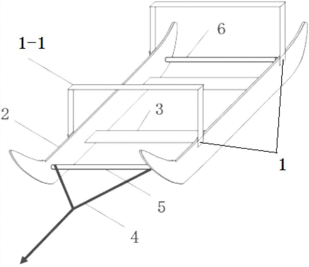
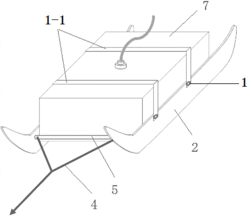
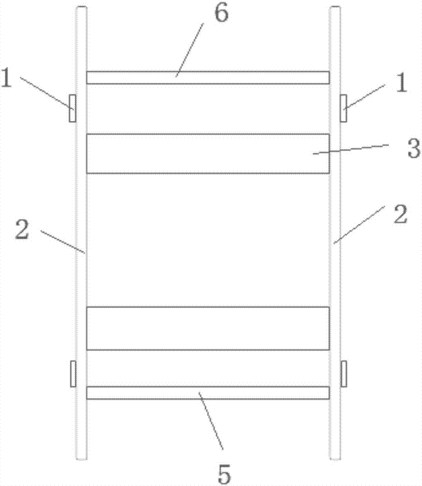
[0057] Such as Figure 1-3As shown, in order to prepare a boot for a 100MHz ground-penetrating radar antenna with a bottom area of ​​45mm×650mm, boot straps 1-1 made of elastic bands (one for the front and the other for a total of two) are used to fix the parts through the boot strap 1. Fixed on the upper part of the two skateboards 2. Two nylon skateboards with curved front ends are placed in parallel with an inner distance of 45 mm. They are fixedly connected by two nylon support base plates 3 with a width of 60 mm and a thickness of 6 mm. The diameter of the towing rope 4 is provided. Be fixed on the front part between two slide plates 2 for the wooden drag post 5 of 2cm, the afterbody of two slide plates 2 fixes a wooden support block post 6, distance between drag row post 5 and support block post 6 is 650mm.

[0058] Such as figure 2 As shown, when in use, the ground penetrating radar antenna 7 is placed in the boots, so that the bottom plane of the ground penetrating r...

Embodiment 2

[0067] The difference between this embodiment and embodiment 1 is:

[0068] The connection between the support post 6 and the slide plate 2 is set to be flexibly connected,

[0069] Buckles and fasteners are provided at the two ends of the support column 6, and a sliding slot is provided at the corresponding position on the slide plate 2. The buckle and the fastener cooperate to fix the support column 6 on the slide plate 2, and the sliding slot is used The ground penetrating radar antenna 7 of different sizes can be adapted to adjust the position of the support post 6 .

Embodiment 3

[0071] The difference between this embodiment and embodiment 1 is:

[0072] Such as Figure 4 As shown, in order to adapt to the geological radar detection of slopes such as roads and railways, and to avoid sliding and side slipping during the towing process of the ground-penetrating radar antenna 7 mounted on the boots, the bottom of the skateboard 2 is set in a wave shape, and of course it can also be set in a sawtooth shape. , other device structures are the same as in Embodiment 1.

[0073] The ground penetrating radar antenna boot provided in this embodiment is convenient to use on slopes after planting grass and low shrubs, and is especially suitable for use in slope detection projects such as roads and railways to ensure stability during detection.


PUM


Abstract

A boot for ground penetrating radar antennas comprises two slide plates, at least one support bottom plate, and a drag column. The two slide plates are fixedly connected by the at least one support bottom plate and the drag column. The two slide plates are arranged in bilateral symmetry and in parallel. The two ends of the drag column are respectively fixed to the front ends of the two slide plates. The boot for ground penetrating radar antennas is further equipped with boot laces. Boot lace fixing components used for fixing the boot laces are arranged at corresponding positions on the outer sides of the upper parts of the two slide plates. A drag rope is fixed to the drag column. When a ground penetrating radar antenna is used together with the boot for ground penetrating radar antennas provided by the invention, the ground penetrating radar antenna can advance smoothly in a complicated site. The boot for ground penetrating radar antennas is suitable for use on grasslands, in mortar rubble places and on slopes after cutting of low shrubs, is especially suitable for use in highway, railway and other slope detection projects, and is simple in structure and easy to operate.

Description

technical field [0001] The invention relates to an auxiliary equipment for ground penetrating radar on-site construction, in particular to a boot for ground penetrating radar antennas, which is suitable for use in sites with uneven ground surfaces that require geological exploration, and is especially suitable for hidden danger exploration of geological slopes and retaining walls use. Background technique [0002] As a geophysical exploration method, one of the key factors to ensure the detection effect and implementation efficiency of ground penetrating radar is the flat surface of the detected medium. However, such as roads, railways, and slopes of rivers and dams, there are generally weeds and shrubs. , some sites are still masonry rubble structural surfaces. When geological radar is used on such sites, the radar antenna is affected by weeds and shrub roots after felling, making it very inconvenient to drag. Hard cement, rock and other structural surfaces will also Heavy...

Claims


Application Information

Patent Timeline
Patent Type & Authority Applications(China)
IPC IPC(8): G01V3/17H01Q1/22H01Q1/12
CPCG01V3/17H01Q1/12H01Q1/225
Inventor 朱德兵冯德山章游斌
Owner CENT SOUTH UNIV
Learn More