Gloves for Ground Penetrating Radar Antennas
A ground penetrating radar and antenna technology, which is applied to antennas, antenna parts, antenna supports/installation devices, etc., can solve problems such as easy vibration and inaccurate detection, and achieve stable structure, guaranteed stability and beautiful appearance. Effect
- Summary
- Abstract
- Description
- Claims
- Application Information
AI Technical Summary
Problems solved by technology
Method used
Image
Examples
Embodiment 1
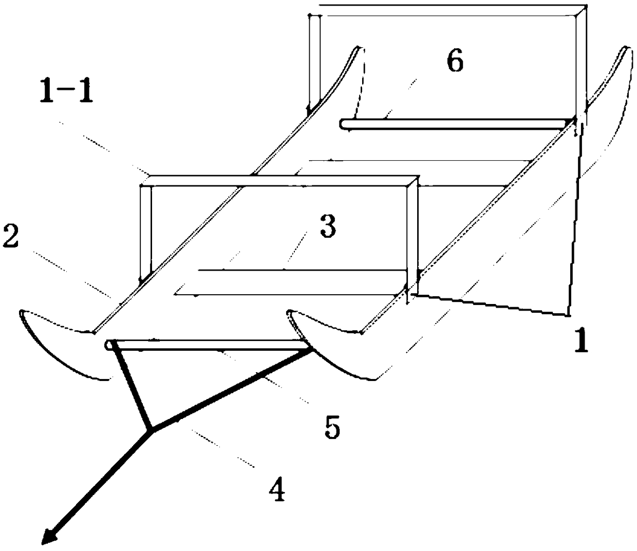
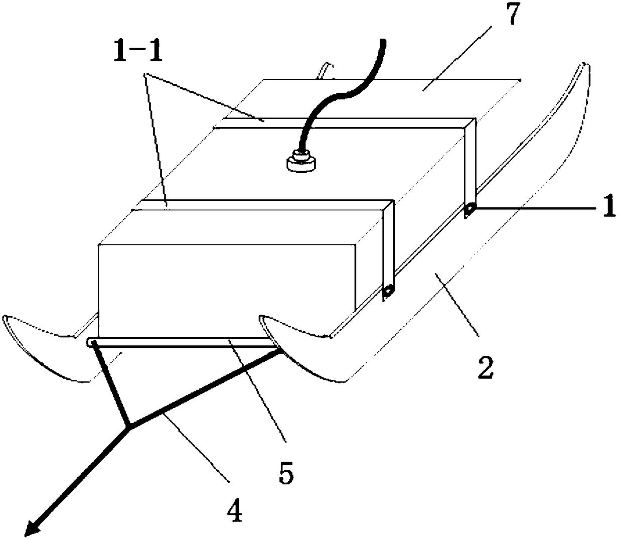
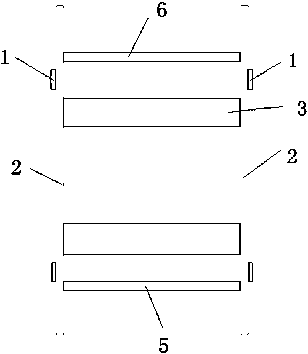
[0057] like Figure 1-3As shown, in order to prepare a boot for a 100MHz ground-penetrating radar antenna with a bottom area of 45mm×650mm, boot straps 1-1 made of elastic bands (one for the front and the other for a total of two) are used to fix the parts through the boot strap 1. Fixed on the upper part of the two skateboards 2. Two nylon skateboards with curved front ends are placed in parallel with an inner distance of 45 mm. They are fixedly connected by two nylon support base plates 3 with a width of 60 mm and a thickness of 6 mm. The diameter of the towing rope 4 is provided. Be fixed on the front part between two slide plates 2 for the wooden drag post 5 of 2cm, the afterbody of two slide plates 2 fixes a wooden support block post 6, distance between drag row post 5 and support block post 6 is 650mm.
[0058] like figure 2 As shown, when in use, the ground penetrating radar antenna 7 is placed in the boots, so that the bottom plane of the ground penetrating radar a...
Embodiment 2
[0067] The difference between this embodiment and embodiment 1 is:
[0068] The connection between the support post 6 and the slide plate 2 is set to be flexibly connected,
[0069] Buckles and fasteners are provided at the two ends of the support column 6, and a sliding slot is provided at the corresponding position on the slide plate 2. The buckle and the fastener cooperate to fix the support column 6 on the slide plate 2, and the sliding slot is used The ground penetrating radar antenna 7 of different sizes can be adapted to adjust the position of the support post 6 .
Embodiment 3
[0071] The difference between this embodiment and embodiment 1 is:
[0072] like Figure 4 As shown, in order to adapt to the geological radar detection of slopes such as roads and railways, and to avoid sliding and side slipping during the towing process of the ground-penetrating radar antenna 7 mounted on the boots, the bottom of the skateboard 2 is set in a wave shape, and of course it can also be set in a sawtooth shape. , other device structures are the same as in Embodiment 1.
[0073] The ground penetrating radar antenna boot provided in this embodiment is convenient to use on slopes after planting grass and low shrubs, and is especially suitable for use in slope detection projects such as roads and railways to ensure stability during detection.
PUM
 Abstract
Description
Claims
Application Information
 - R&D
- Intellectual Property
- Life Sciences
- Materials
- Tech Scout
- Unparalleled Data Quality
- Higher Quality Content
- 60% Fewer Hallucinations
Browse by: Latest US Patents, China's latest patents, Technical Efficacy Thesaurus, Application Domain, Technology Topic, Popular Technical Reports.
© 2025 PatSnap. All rights reserved.Legal|Privacy policy|Modern Slavery Act Transparency Statement|Sitemap|About US| Contact US: help@patsnap.com


