
Self-cooling type conductive contact piece and connector

A conductive contact, self-cooling technology, applied in conductive connections, contact parts, welding/welding connections, etc., can solve the problem that the current cannot pass a large current for a long time, the contacts cannot be used continuously for a long time, and the normal use of the contacts is affected, etc. The problem is to achieve the effect of simple and convenient structure, good cooling, and convenient disassembly and assembly.

Active Publication Date: 2017-06-23
CHINA AVIATION OPTICAL-ELECTRICAL TECH CO LTD
View PDF4 Cites 27 Cited by
  • Summary
  • Abstract
  • Description
  • Claims
  • Application Information

AI Technical Summary

Problems solved by technology

[0002] The conductive contact will generate a certain amount of heat due to the existence of resistance when the current passes, resulting in the temperature rise of the contact. In order to solve the problem of temperature rise of the contact, it is usually achieved by controlling the magnitude of the current, that is, when the contact When the heat is too large, the temperature rise of the contact can be reduced by reducing the current. When the temperature is too high, it is even necessary to stop the current input, and then conduct the current input after the contact is cooled, which makes the contact impossible. Continuous use for a long time, or the current passing through cannot pass a large current for a long time, which will affect the normal use of the contacts and affect the work efficiency

Method used


Image

  • Self-cooling type conductive contact piece and connector
  • Self-cooling type conductive contact piece and connector
  • Self-cooling type conductive contact piece and connector

Examples


Embodiment Construction

[0047] Embodiments of the present invention will be further described below in conjunction with the accompanying drawings.

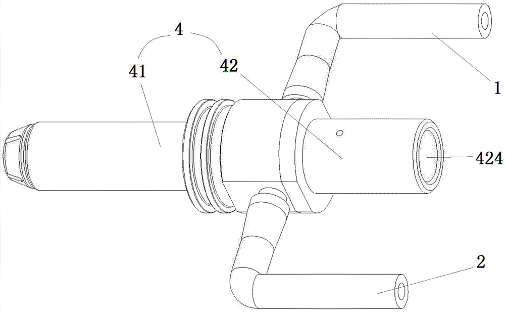
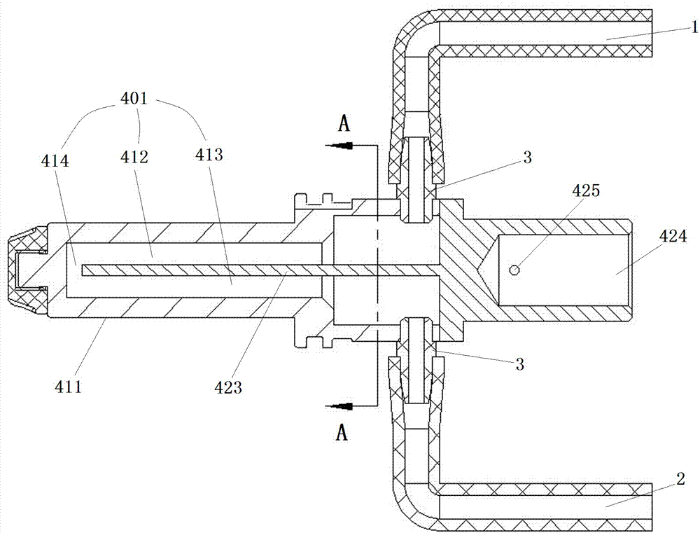
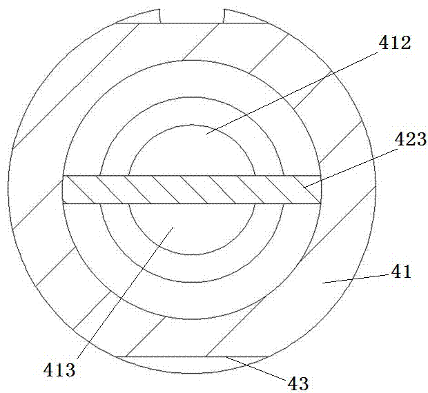
[0048] Specific embodiments of the connector of the present invention, such as Figure 1 to Figure 12As shown, the connector includes a connector housing on which conductive contacts are provided. The connector housing is the prior art, which is not shown in the figure and will not be described again. The conductive contact 4 includes a contact body. The contact body is welded by a pin end 41 and a crimping end 42. The pin end 41 has an inserting portion 411 that is adapted to be inserted into an adapted contact. The inserting portion 411 is used as a conductive part and is also a part that generates heat. The crimping end 42 has a crimping hole 424 for connecting with the cable. The side wall of the crimping hole 424 is provided with a screw hole 425 in the radial direction for inserting the cable. After the crimping hole 424, the cable is crimped and ...


PUM


Abstract

The present invention relates to a self-cooling type conductive contact piece and a connector. The connector comprises a connector housing and a self-cooling type conductive contact piece arranged in the connector housing; the self-cooling type conductive contact piece comprises a contact piece body; a liquid flow channel in which a cooling liquid circulates to make heat on a contact piece body discharged with the cooling liquid is arranged in the contact piece body; and two ends of the liquid flow channel are provided with a liquid inlet and a liquid outlet respectively. The liquid flow channel is arranged in the self-cooling type conductive contact piece; the insulating cooling liquid can directly flow into the liquid flow channel; the cooling liquid enters the contact piece from the liquid inlet and then circulates in the contact piece; in the circulation process, the cooling liquid takes away the heat on the contact piece, flows out through the liquid outlet and cools outside; and therefore, circulatory heat exchange can be realized, and heat conduction and heat dissipation of the contact piece can be realized. The flow rate of the cooling liquid can be adjusted according to the amount of the heat emitted by the contact piece, and therefore, the contact piece can be well cooled under the premise that current passing through the contact piece is not decreased.

Description

technical field [0001] The invention relates to a self-cooling conductive contact piece and a connector. Background technique [0002] The conductive contact will generate a certain amount of heat due to the existence of resistance when the current passes, resulting in the temperature rise of the contact. In order to solve the problem of temperature rise of the contact, it is usually achieved by controlling the magnitude of the current, that is, when the contact When the heat is too large, the temperature rise of the contact can be reduced by reducing the current. When the temperature is too high, it is even necessary to stop the current input, and then conduct the current input after the contact is cooled, which makes the contact impossible. Long-term continuous use, or the passing current cannot pass through a large current for a long time, which will affect the normal use of the contacts and affect the work efficiency. Contents of the invention [0003] The purpose of ...

Claims


Application Information

Patent Timeline
IPC IPC(8): H01R13/04H01R4/02H05K7/20
CPCH01R4/029H01R13/04H05K7/20218
Inventor 顾文武张培
Owner CHINA AVIATION OPTICAL-ELECTRICAL TECH CO LTD
Learn More