
Head structure of smearing device

A technology of applicator head and head, applied in the field of head structure of applicator device, can solve problems such as complicated structure of applicator, and achieve the effect of good visual effect, simple structure and smooth line

Inactive Publication Date: 2017-06-27
SHYA HSIN PACKAGING IND CHINA
View PDF7 Cites 5 Cited by
  • Summary
  • Abstract
  • Description
  • Claims
  • Application Information

AI Technical Summary

Problems solved by technology

[0004] In order to overcome the above-mentioned defects, the present invention provides a head structure of a smearing device, which can solve the technical problems of complex structures existing in existing applicators

Method used


Image

  • Head structure of smearing device
  • Head structure of smearing device
  • Head structure of smearing device

Examples


Embodiment 1

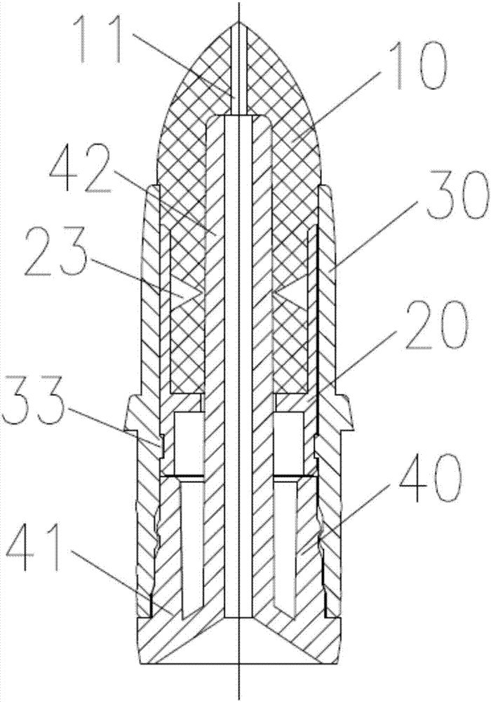
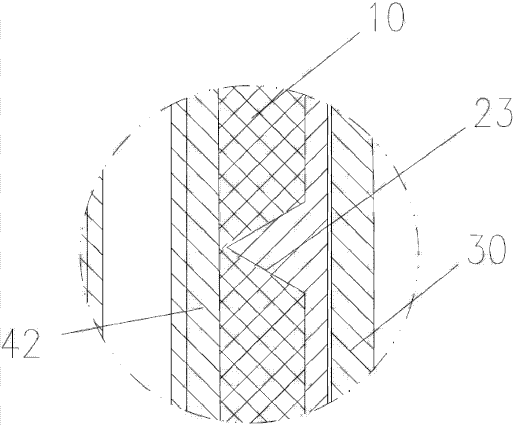
[0035] Embodiment 1: as figure 1 , Figure 4-10 As shown, a head structure of a smearing device includes: a sleeve 30, the sleeve 30 is hollow, and the sleeve 30 includes a first connecting portion 31 and a second connecting portion 32; a smearing head 10 , the said smear head is provided with a through hole 11, said smear head 10 comprises a head 12 and an annular tail 13; a clamp 20, said clamp 20 comprises a bottom 21 and at least one pair of symmetrical and elastic parts connected to the bottom 21 Teeth 22, the annular tail 13 of the smear head is placed between the tooth buckles 22, the tooth buckle 22 can clamp the smear head 10, the clamp 20 is placed in the sleeve, and the clamp 20 is placed in the sleeve. The bottom 21 is fixedly connected to the first connecting portion 31 of the sleeve, and the head 12 of the applicator head protrudes from the sleeve 30; a fixed seat 4, the fixed seat includes a base 41 and a hollow space connected to the base Fixed rod 42, the ba...

Embodiment 2

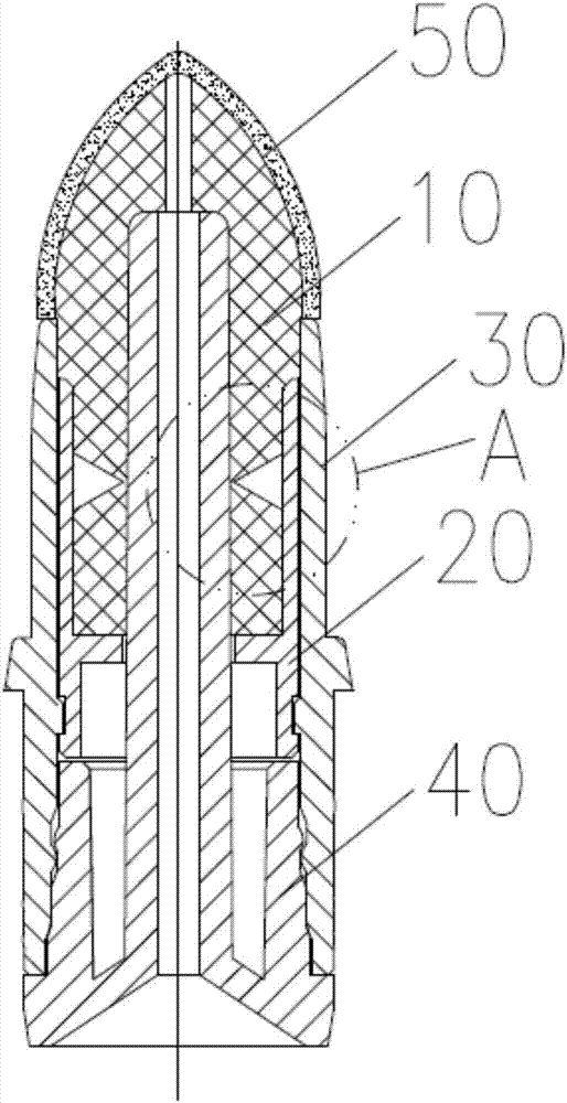
[0040] Embodiment 2: as Figure 2-3 As shown, the difference between this embodiment and Embodiment 1 is only that: the head 12 of the applicator head is also planted with a layer of fluff 50 . According to needs, it can be used after flocking on the applicator head, so that the touch of the applicator head is softer, because the fluff has adsorption force, and the effect of the applicator is more delicate.

[0041] The operating process of the present invention is:

[0042] Installation process: attached Figure 11 As shown, the arrow in the figure is the instruction mark of the installation process. First, place the applicator head 10 in the jig 20, and then insert the jig 20 into the first connecting part 31 of the sleeve 30 until the protrusion in the first connecting part 33 into the groove 24 of the bottom 21 of the fixture, and then insert the fixing seat 40 into the second connecting part 32 of the sleeve, the base 41 of the fixing seat is engaged with the second con...


PUM


Abstract

The invention relates to a head structure of a smearing device. The head structure comprises a sleeve, a smearing head, a clamp and a fixed base; the sleeve is hollow and comprises a first connecting part and a second connecting part; a through hole is formed in the smearing head, and the smearing head comprises a head and an annular tail; the clamp comprises a bottom and at least one pair of symmetric and elastic toothed buckles connected with the bottom, the annular tail of the smearing head is arranged between the toothed buckles, and the toothed buckles can clamp the smearing head; the bottom of the clamp is fixedly connected with the first connecting part of the sleeve; the fixed base comprises a base and a hollow fixed rod connected to the base, the base of the fixed base is fixedly connected with the second connecting part of the sleeve, one end of the fixed rod is inserted into the through hole of the smearing head and communicated with the through hole, and the other end of the fixed rod is communicated with the outside. The head structure of the smearing device is simple in structure, high in practicability, convenient to carry and capable of being used repeatedly.

Description

technical field [0001] The invention relates to a cosmetic application device, in particular to a head structure of the application device. Background technique [0002] With the growth of the economy and the progress of the society, people pay more and more attention to their appearance, and the demand for cosmetics and skin care products is also relatively increased. In today's society, not only women but also men use skin care products or cosmetics, based on market demand. With the improvement of the market, more and more different types of skin care products and cosmetics are appearing on the market at the same time. [0003] Liquids of various colors are housed in some existing makeup brushes, and one end of the makeup pencil is provided with a hairbrush, and the liquid in the makeup pencil flows in the hairbrush and dyes the bristles on the hairbrush. When people use the makeup brush, the bristles of the hairbrush are brushed on the corresponding parts of the human bo...

Claims


Application Information

Patent Timeline
Patent Type & Authority Applications(China)
IPC IPC(8): A45D40/20A45D40/26
CPCA45D40/20A45D40/26A45D34/04A45D2040/0062A45D2040/201A45D2040/204A45D2200/10A45D34/042
Inventor 钟华詹玲郎
Owner SHYA HSIN PACKAGING IND CHINA
Learn More