Eureka AIR delivers breakthrough ideas for toughest innovation challenges, trusted by R&D personnel around the world.

Stamping blanking die with switching mechanism

A technology of switching mechanism and blanking dies, applied in the field of stamping blanking dies, can solve the problems of occupying more die installation space, large processing and research workload, and increased die cost, so as to reduce development costs and purchases. , the effect of saving processing time and production costs

Inactive Publication Date: 2017-06-27
ANHUI JIANGHUAI AUTOMOBILE GRP CORP LTD
View PDF7 Cites 4 Cited by
  • Summary
  • Abstract
  • Description
  • Claims
  • Application Information

AI Technical Summary

Problems solved by technology

In addition, the conventional blanking die is designed with a pressing core or a pressing plate, and the pressing core or pressing plate is mostly installed on the upper die base through working bolts, and is used for blanking and punching sheet cutting. Press the sheet material tightly, but this kind of pressing plate or pressing core requires a large amount of processing and research and matching, which leads to an increase in mold cost and takes up a lot of internal installation space in the mold

Method used


Image

  • Stamping blanking die with switching mechanism
  • Stamping blanking die with switching mechanism
  • Stamping blanking die with switching mechanism

Examples


Embodiment Construction

[0034] Embodiments of the present invention are described in detail below, examples of which are shown in the drawings, wherein the same or similar reference numerals designate the same or similar elements or elements having the same or similar functions throughout. The embodiments described below by referring to the figures are exemplary only for explaining the present invention and should not be construed as limiting the present invention.

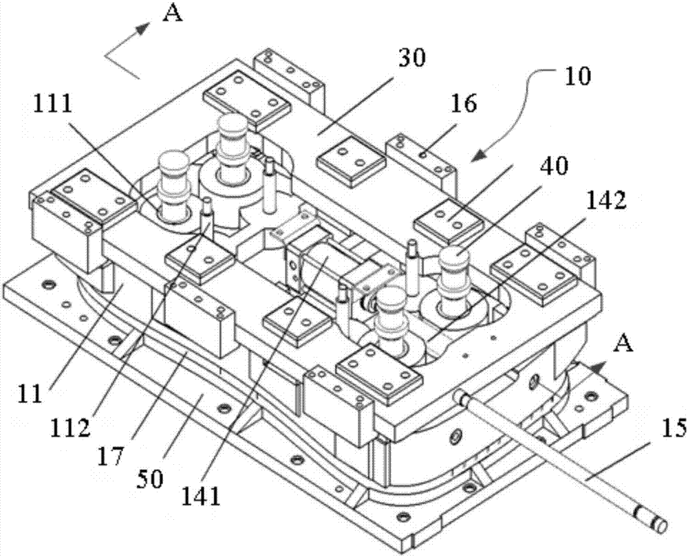
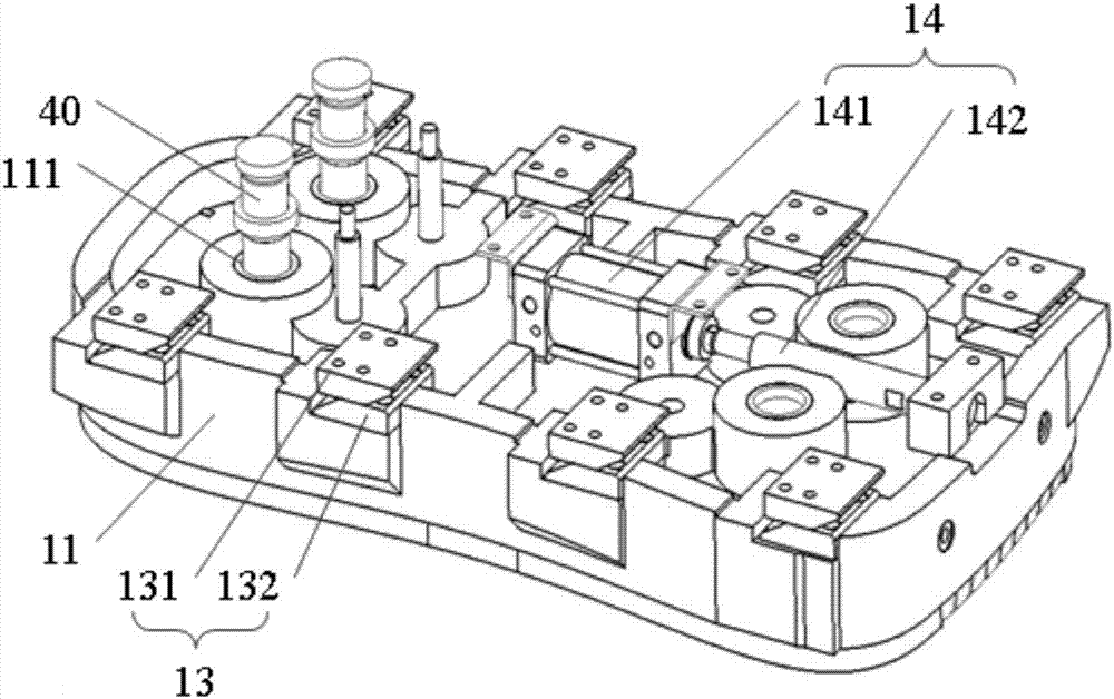
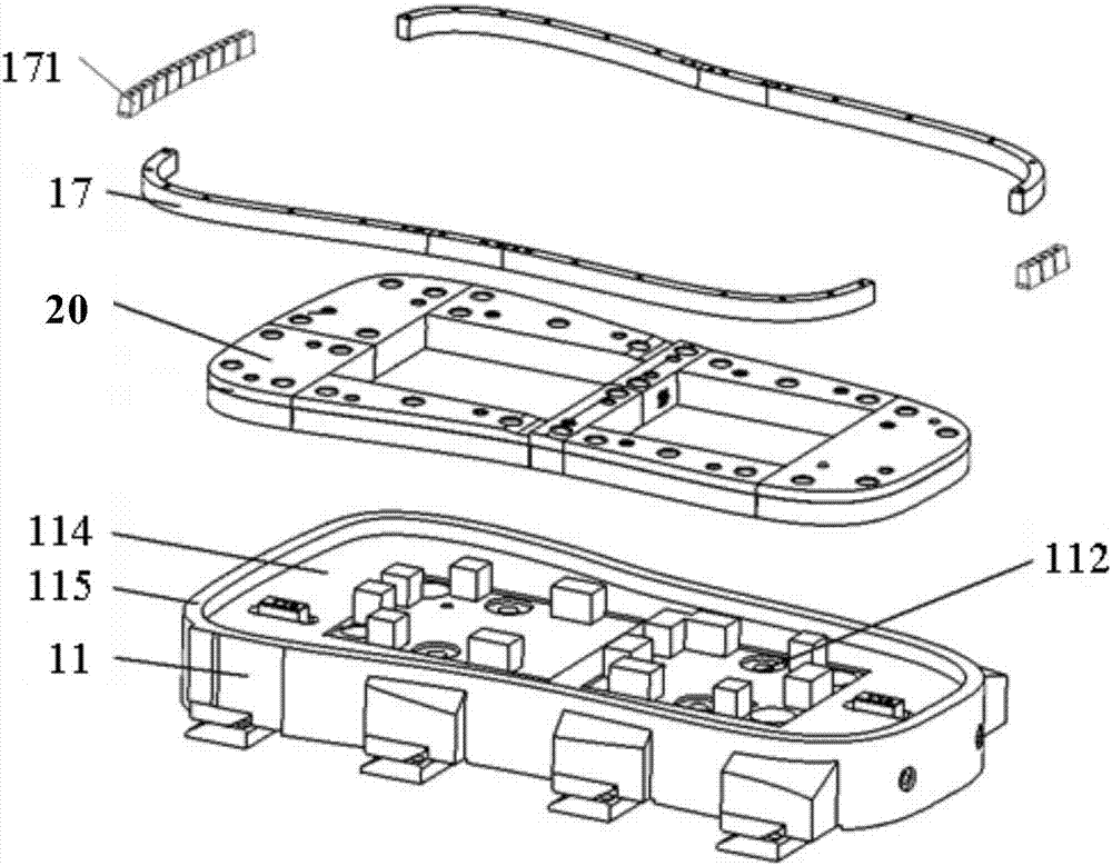
[0035] figure 1 It is a schematic structural diagram of the switching mechanism 10 of the stamping blanking die with switching mechanism provided by the embodiment of the present invention, figure 2 A schematic diagram of the partial structure of the switching mechanism 10 of the stamping blanking die with switching mechanism provided by the embodiment of the present invention, image 3 An exploded view of the assembly of the switching mechanism and the trimming die of the stamping blanking die with a switching mechanism provided for t...


PUM


Abstract

The invention provides a stamping blanking die with a switching mechanism. The stamping blanking die comprises an upper die base, a lower die base, the switching mechanism, a trimming female die and a sliding plate. The lower die base is provided with a trimming male die. The switching mechanism comprises an installation base and an elastic pressing ring. The installation base is connected with the upper die base through a compression spring. The elastic pressing ring is formed by splicing multiple pressing blocks in a strip block shape. The elastic pressing ring is located on the outer ring of the bottom end of the installation base. The trimming female die is fixedly connected with the end face, away from the upper die base, of the installation base, and the sliding plate is in sliding connection with the installation base and located between the installation base and the upper die base. According to the stamping blanking die, no pressing plate structure needs to be designed, the purchasing, machining, lapping-in and assembling machining amount of the whole pressing plate is reduced, the die development cost is reduced, two kinds of side bodies are machined through one die, and machining time and the production cost are saved.

Description

technical field [0001] The invention relates to the technical field of automobile parts processing, in particular to a stamping blanking die with a switching mechanism. Background technique [0002] At present, with the development of society, more and more commercial vehicles appear in people's field of vision. There are various types of commercial vehicles, one of which is the type with a sliding door on one side, and the two sides of this type The surrounding structure is basically the same, the only difference is that a door opening needs to be set on the side with the sliding door. In order to save mold and processing time and cost, it is necessary to develop a mold that can process the two side panels of this commercial vehicle at the same time. In addition, the conventional blanking die is designed with a pressing core or a pressing plate, and the pressing core or pressing plate is mostly installed on the upper die base through working bolts, and is used for blanking ...

Claims


Application Information

Patent Timeline
Patent Type & Authority Applications(China)
IPC IPC(8): B21D37/02B21D53/88
CPCB21D37/02B21D53/88
Inventor 王海玲陈世涛张金贵李辉田冰星高双明
Owner ANHUI JIANGHUAI AUTOMOBILE GRP CORP LTD
Why Eureka
Eureka Blog
Learn More