Supercharge Your Innovation With Domain-Expert AI Agents!

Automatic clamping device for small workpiece

A technology for automatic clamping and small workpieces, which is applied in clamping devices, positioning devices, metal processing mechanical parts, etc., and can solve the problems of poor sound quality, large position tolerance, and low production efficiency of musical instruments.

Inactive Publication Date: 2017-06-27
曹诗晴
View PDF0 Cites 0 Cited by
  • Summary
  • Abstract
  • Description
  • Claims
  • Application Information

AI Technical Summary

Problems solved by technology

It is a very difficult process to process threaded holes with small distances and small sizes on such a small base plate. Therefore, ordinary workers use the method of hand-held workpieces to process individually, but this processing method has the following disadvantages: Machining the threaded holes will lead to a large position tolerance of several threaded holes, which will cause uneven installation of the parts on the bottom plate, which will cause poor sound quality of the octave
But this method also has the following disadvantages: because this method is to place two or more base plates in parallel in advance, clamp them with a clamp, and then perform drilling and tapping. After disassembling the clamping device, the processed workpieces are taken out, and then another batch of workpieces to be processed is placed again. Therefore, the production efficiency is very low, which is not conducive to the realization of automatic production

Method used


Image

  • Automatic clamping device for small workpiece
  • Automatic clamping device for small workpiece

Examples


Embodiment Construction

[0015] The present invention will be described in further detail below in conjunction with the accompanying drawings and specific embodiments.

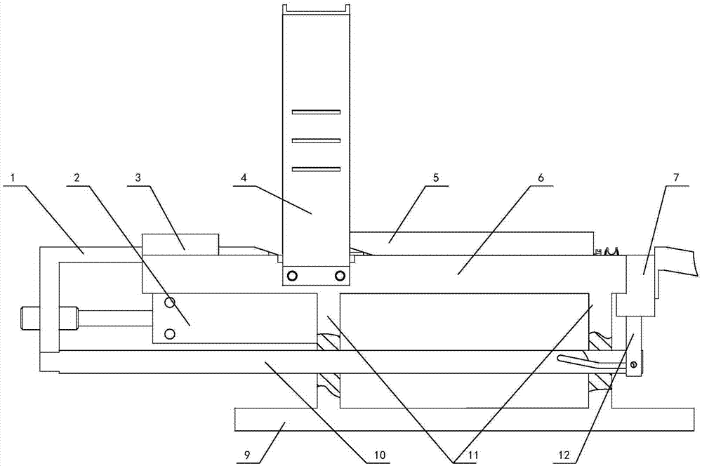
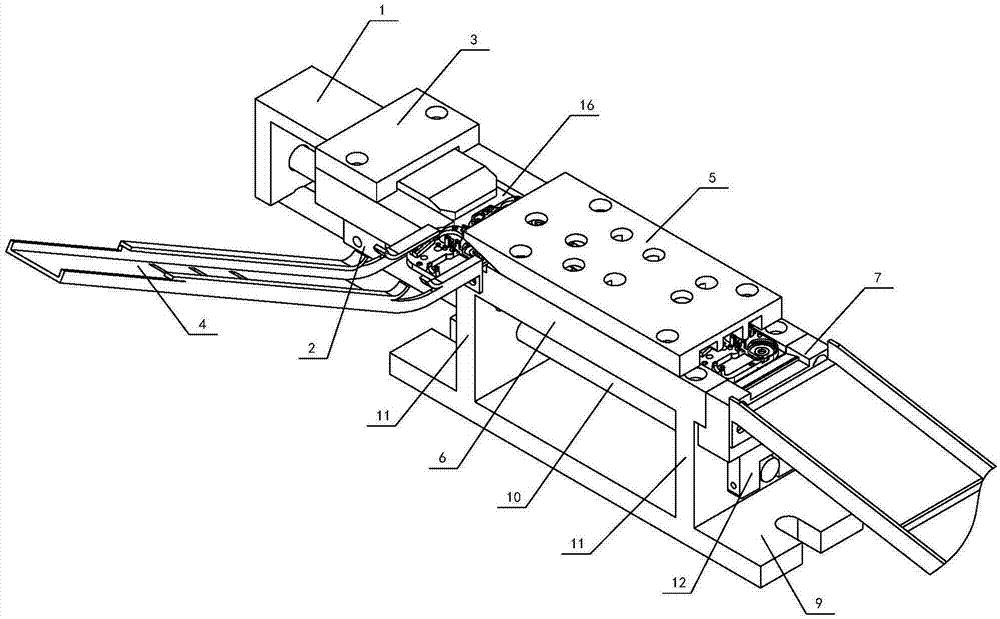
[0016] Depend on figure 1 , figure 2 As can be seen from the structural schematic diagram of the automatic clamping device for small workpieces of the present invention, it includes a positioning frame and a feed guide rail 4, the top surface of the positioning frame has a workpiece positioning groove 8 for placing workpieces, and the feed guide rail 4 is connected to the positioning frame. side of the upper shelf. It also includes a jacking device, a cylinder 2, a pull rod 10, a push plate 1 and a push plate press plate 3; On the positioning frame, the piston rod in the cylinder 2 is connected with the push plate 1; one end of the push plate 1 is located between the push plate pressing plate 3 and the upper plate 6 and is slidably matched with the workpiece positioning groove 8, and the other end is passed through the pull rod 10 ...


PUM


Abstract

The invention discloses an automatic clamping device for small workpieces, which comprises a positioning frame and a feeding guide rail (4), the top surface of the positioning frame has a workpiece positioning groove (8) for placing workpieces, and the feeding guide rail (4) It is connected to the side of the upper part of the positioning frame; it also includes a jacking device, a cylinder (2), a pull rod (10), a push plate (1) and a push plate pressing plate (3); wherein, the pushing plate pressing plate (3) is connected to the positioning frame The end of the top surface of the cylinder (2) is connected on the positioning frame near the push plate pressing plate (3), and the piston rod in the cylinder (2) is connected with the push plate (1); one end of the push plate (1) is located on the push plate The pressing plate (3) and the upper plate (6) are slidingly matched with the workpiece positioning groove (8), and the other end is connected with the ejecting device through a pull rod (10). After the above structure is adopted, the clamping device can automatically perform clamping and loosening operations through the control of the cylinder, which greatly improves the production efficiency and is conducive to the realization of automatic production.

Description

technical field [0001] The invention relates to the field of mechanical processing, in particular to an automatic clamping device for small workpieces suitable for drilling and tapping of smaller parts. Background technique [0002] In mechanical processing production, in order to ensure product quality and improve labor production efficiency, fixture is one of the indispensable machine tool accessories. Especially for parts with small size, such as the installation base plate in the octave, not only the size of the part itself is small, but also multiple threaded holes need to be processed on the base plate, even some threaded holes have a size of M1.6, and the distance between the threaded holes The distance is also very small, so the fixture is particularly important. It is a very difficult process to process threaded holes with small distances and small sizes on such a small base plate. Therefore, ordinary workers use the method of hand-held workpieces to process indivi...

Claims


Application Information

Patent Timeline
IPC IPC(8): B23Q3/08
CPCB23Q3/08B23Q2703/04
Inventor 曹诗晴
Owner 曹诗晴
Features
  • R&D
  • Intellectual Property
  • Life Sciences
  • Materials
  • Tech Scout
  • Unparalleled Data Quality
  • Higher Quality Content
  • 60% Fewer Hallucinations
Learn More