Novel wall drilling equipment for construction site

A construction site and drilling equipment technology, applied in stone processing equipment, working accessories, manufacturing tools, etc., can solve the problems of time-consuming and labor-intensive drilling, inability to drill accurately, high risk of drilling process, etc.

Active Publication Date: 2017-06-27
CHINA RAILWAY BEIJING ENG GRP CO LTD +2
View PDF5 Cites 6 Cited by
  • Summary
  • Abstract
  • Description
  • Claims
  • Application Information

AI Technical Summary

Problems solved by technology

[0006] In order to overcome the disadvantages that the current manual drilling of the wall cannot be performed more accurately, the drilling process has high risk, and the drilling process is time-consuming and laborious, the technical pr

Method used


Image

  • Novel wall drilling equipment for construction site
  • Novel wall drilling equipment for construction site
  • Novel wall drilling equipment for construction site

Examples


Embodiment 1

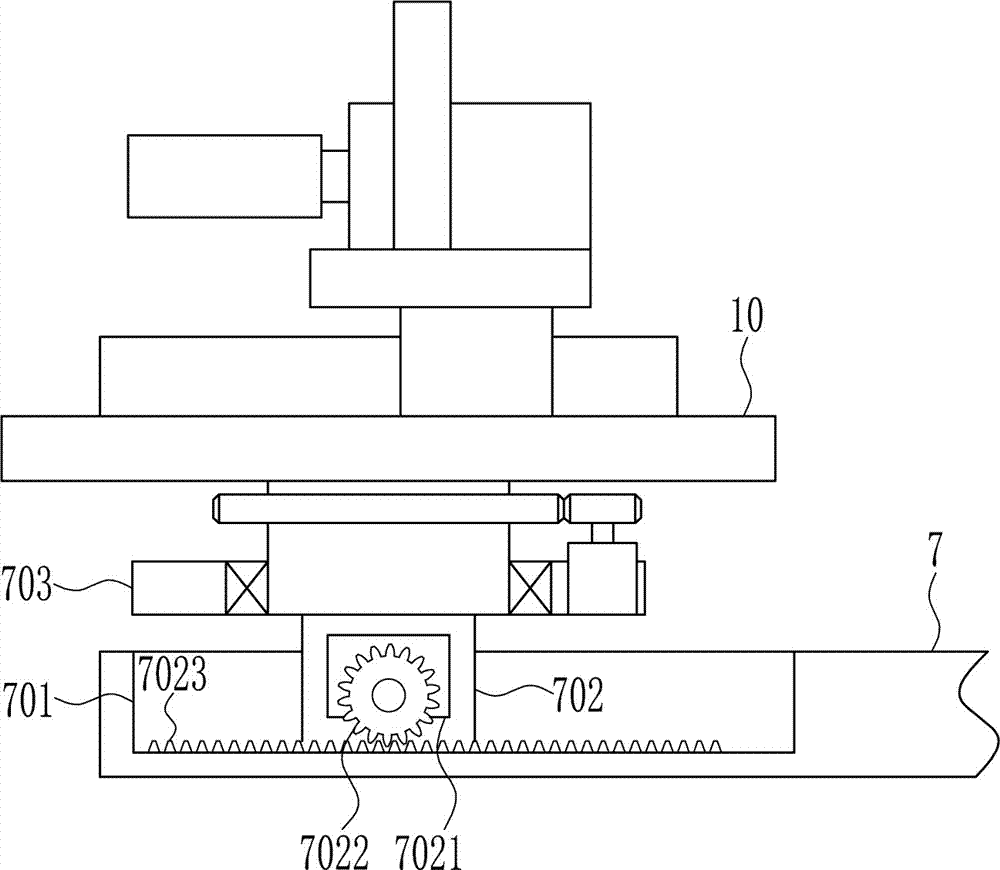
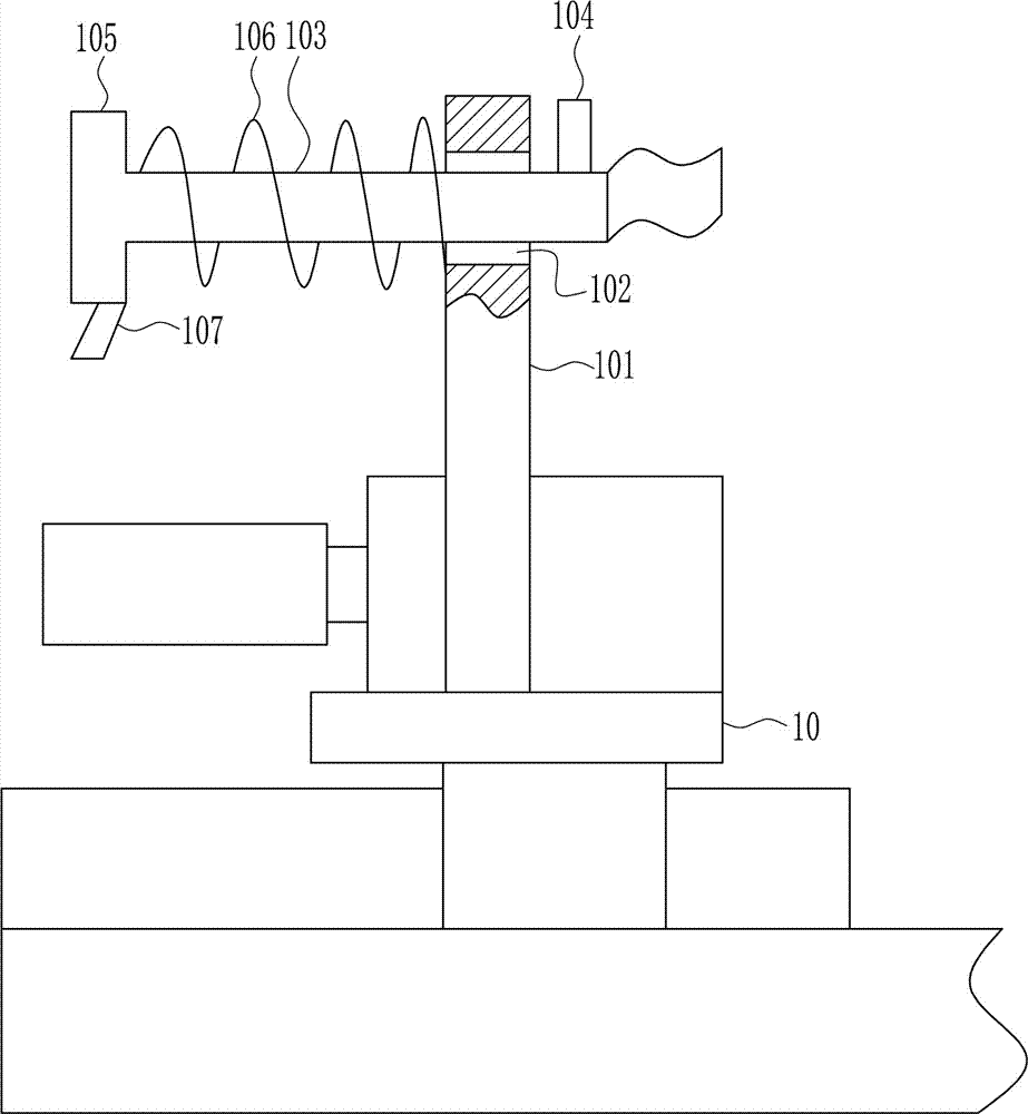
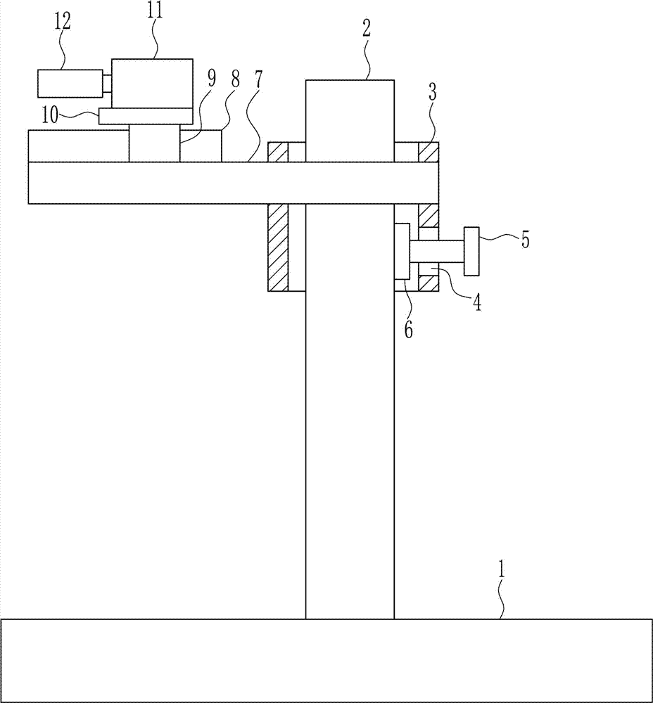
[0037] A new type of wall drilling equipment for construction sites, such as Figure 1-6 As shown, it includes a bottom plate 1, a first guide rail 2, a first guide sleeve 3, a screw rod 5, a pressure block 6, a support plate 7, a first slide rail 8, a first slider 9, a first fixing plate 10, a first The motor 11 and the drill bit 12, the upper middle part of the base plate 1 is installed with the first guide rail 2 by welding, the first guide rail 2 is slidably connected with the first guide sleeve 3, and the lower right side of the first guide sleeve 3 has a threaded hole 4, A screw 5 is placed in the threaded hole 4, and the screw 5 cooperates with the threaded hole 4. The left end of the screw 5 is rotatably connected with the first pressure block 6, and the front side of the first guide sleeve 3 is installed with a support plate 7 by welding. The first slide rail 8 is installed on the upper left side by welding, the first slide rail 8 is slidably connected with the first ...

Embodiment 2

[0039] A new type of wall drilling equipment for construction sites, such as Figure 1-6 As shown, it includes a bottom plate 1, a first guide rail 2, a first guide sleeve 3, a screw rod 5, a pressure block 6, a support plate 7, a first slide rail 8, a first slider 9, a first fixing plate 10, a first The motor 11 and the drill bit 12, the upper middle part of the base plate 1 is installed with the first guide rail 2 by welding, the first guide rail 2 is slidably connected with the first guide sleeve 3, and the lower right side of the first guide sleeve 3 has a threaded hole 4, A screw 5 is placed in the threaded hole 4, and the screw 5 cooperates with the threaded hole 4. The left end of the screw 5 is rotatably connected with the first pressure block 6, and the front side of the first guide sleeve 3 is installed with a support plate 7 by welding. The first slide rail 8 is installed on the upper left side by welding, the first slide rail 8 is slidably connected with the first ...

Embodiment 3

[0042] A new type of wall drilling equipment for construction sites, such as Figure 1-6 As shown, it includes a bottom plate 1, a first guide rail 2, a first guide sleeve 3, a screw rod 5, a pressure block 6, a support plate 7, a first slide rail 8, a first slider 9, a first fixing plate 10, a first The motor 11 and the drill bit 12, the upper middle part of the base plate 1 is installed with the first guide rail 2 by welding, the first guide rail 2 is slidably connected with the first guide sleeve 3, and the lower right side of the first guide sleeve 3 has a threaded hole 4, A screw 5 is placed in the threaded hole 4, and the screw 5 cooperates with the threaded hole 4. The left end of the screw 5 is rotatably connected with the first pressure block 6, and the front side of the first guide sleeve 3 is installed with a support plate 7 by welding. The first slide rail 8 is installed on the upper left side by welding, the first slide rail 8 is slidably connected with the first ...


PUM


Abstract

The invention relates to drilling equipment, in particular to novel wall drilling equipment for a construction site. The novel wall drilling equipment for the construction site is provided for achieving the technical effects that the equipment can conduct accurate drilling, damage is small in the drilling process, and time and labor are saved in the drilling process. In order to achieve the technical effects, the novel wall drilling equipment for the construction site, provided by the invention, comprises a bottom plate, a first guide rail, a first guide sleeve, a screw rod, a pressing block, a supporting plate, a first slide rail and the like. The first guide rail is mounted in the middle of the upper side of the bottom plate in a welded mode. The first guide sleeve is connected to the first guide rail in a sliding mode. A threaded hole is formed in the lower portion of the right side of the first guide sleeve. The screw rod is arranged in the threaded hole. The novel wall drilling equipment for the construction site achieves the effects that the equipment can conduct accurate drilling, danger is small in the drilling process, and time and labor are saved in the drilling process. The novel wall drilling equipment for the construction site can move a drill bit automatically by adopting a rotating device and a feeding device.

Description

technical field [0001] The invention relates to a drilling device, in particular to a novel wall drilling device for a construction site. Background technique [0002] Using a drill to process a hole in a solid material is called drilling. The hole processing of various parts is completed by machine tools such as turning, boring, and milling, and a large part is completed by fitters using drilling machines and drilling tools (drills, reamers, reamers, etc.). When drilling a hole on a drilling machine, in general, the drill bit should complete two movements at the same time; the main movement, that is, the rotational movement of the drill bit around the axis (cutting movement); the auxiliary movement, that is, the linear movement of the drill bit against the workpiece along the axis direction ( Feed movement), when drilling, mainly due to the shortcomings of the drill bit structure, which affects the processing quality, the processing accuracy is generally below IT10 level, ...

Claims


Application Information

Patent Timeline
IPC IPC(8): B28D1/14B28D7/00B28D7/02
CPCB28D1/14B28D7/005B28D7/02
Inventor 不公告发明人
Owner CHINA RAILWAY BEIJING ENG GRP CO LTD
Why Eureka
Try Eureka