Clamping and positioning device for steel pipe punching

A technology of clamping positioning and positioning device, applied in positioning device, clamping, boring/drilling, etc., can solve problems such as deviation of drill bit, damage to steel pipe and drill bit, deformation of steel pipe, etc., to achieve convenient processing , avoid offset, improve the effect of punching accuracy

Inactive Publication Date: 2021-02-26
潍坊维润金属科技有限公司
View PDF0 Cites 6 Cited by
  • Summary
  • Abstract
  • Description
  • Claims
  • Application Information

AI Technical Summary

Problems solved by technology

[0003] In the prior art, the traditional steel pipe punching usually uses a bench vise to clamp the steel pipe, and even fixes it with a foot pedal. When this method clamps a thinner steel pipe, it is easy to clamp if the clamping is too tight. If the steel pipe is deformed, if the clamping is too loose, it is easy to loosen during drilling, damage the steel pipe and the drill bit, and it is difficult to position when drilling, and the drill bit is prone to deviation when drilling. Therefore, a steel pipe drilling tool is invented. It is necessary to hold the positioning device

Method used


Image

  • Clamping and positioning device for steel pipe punching
  • Clamping and positioning device for steel pipe punching
  • Clamping and positioning device for steel pipe punching

Examples


Embodiment 1

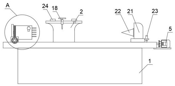
[0034] see Figure 1-9 , a clamping and positioning device for steel pipe drilling, including a workbench 1, and also includes:

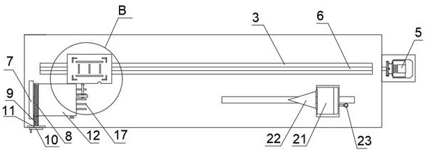
[0035] The mobile seat 2, the upper surface of the workbench 1 is provided with a T-shaped slot 3, and a slide block 4 is slidably connected in the T-shaped slot 3, the side wall of the slide block 4 is provided with a threaded hole, and the slide block 4 The upper surface is fixedly connected with the moving seat 2, and one side of the workbench 1 is fixedly connected with a first servo motor 5, and the output end of the first servo motor 5 is fixedly connected with a screw rod 6, and the screw rod 6 runs through the working The side wall of the table 1 extends into the T-shaped slot 3 and is set, and the screw rod 6 is screwed to the threaded hole, and a positioning device 18 is fixedly connected to one side of the moving base 2 .

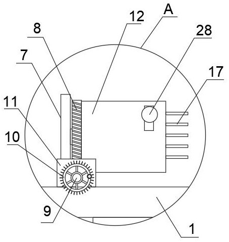
[0036] Steering mechanism, the steering mechanism includes a support plate 7, the side wall of the support plate 7 ...

Embodiment 2

[0044] Based on Example 1, such as Figure 10 , the positioning device 18 includes a connecting rod 187, the connecting rod 187 is slidingly connected to the moving base 2, and the end of the connecting rod 187 away from the moving base 2 is fixedly connected to a bearing 188, and a positioning ring is placed on the bearing 188 189. When drilling, first select positioning rings 189 with different inner diameters according to the outer diameter of the drilling bit and put them in the center of the bearing 188, then slide the connecting rod 187 up and down to make the lower surface of the bearing 188 offset against the upper surface of the steel pipe , then when punching, the drill bit of the drilling equipment passes through the positioning ring 189, thereby avoiding the offset when the drill bit contacts the arc surface of the steel pipe, improving the stability of the drill bit, and by setting the bearing 188, the positioning ring 189 and the drilling bit can be lowered. and ...


PUM

PropertyMeasurementUnit
thicknessaaaaaaaaaa

Abstract

The invention relates to a clamping and positioning device for steel pipe punching. The clamping and positioning device comprises a workbench and further comprises a movable base, a T-shaped groove isformed in the upper surface of the workbench, a sliding block is slidably connected into the T-shaped groove, a threaded hole is formed in the side wall of the sliding block, and the upper surface ofthe sliding block is fixedly connected with the movable base; and one side of the workbench is fixedly connected with a first servo motor. The clamping and positioning device for steel pipe punchingrelates to the technical field of steel pipe machining equipment; the movable base is arranged to be matched with a screw rod and the first servo motor, punching equipment such as a bench drill is installed on the movable base and can be matched with the clamping and positioning device to punch a steel plate, and the first servo motor is used for driving the punching equipment to move, so that punching operation can be accurately conducted on the side wall of a steel pipe; and a steering mechanism is arranged, and a hand wheel can be used for driving a worm wheel to rotate, so that a clampingdevice drives the steel pipe to rotate, and punching is conducted at different positions of the side wall of the steel pipe.

Description

technical field [0001] The invention relates to a clamping and positioning device for steel pipe drilling, which belongs to the technical field of steel pipe processing equipment. Background technique [0002] Steel pipe refers to steel with a hollow section whose length is much greater than its diameter or circumference. According to the cross-sectional shape, it is divided into round, square, rectangular and special-shaped steel pipes; steel pipes are widely used in people's daily production and life. When using steel pipes, it is often necessary to weld, cut and punch steel pipes. [0003] In the prior art, the traditional steel pipe punching usually uses a bench vise to clamp the steel pipe, and even fixes it with a foot pedal. When this method clamps a thinner steel pipe, it is easy to clamp if the clamping is too tight. If the steel pipe is deformed, if the clamping is too loose, it is easy to loosen during drilling, damage the steel pipe and the drill bit, and it is ...

Claims


Application Information

Patent Timeline
Patent Type & Authority Applications(China)
IPC IPC(8): B23Q3/12B23B41/00
CPCB23B41/00B23Q3/12
Inventor 李昕姚毅博
Owner 潍坊维润金属科技有限公司
Why Eureka
Try Eureka