Tensioning machine capable of withdrawing tapes automatically

A tensioning machine and automatic technology, which is applied to the parts of the strapping machine, etc., can solve the problems of operator discomfort, sharp edges of parts, potential safety hazards, etc.

Active Publication Date: 2017-06-27
宁波希赫机械有限公司
View PDF7 Cites 4 Cited by
  • Summary
  • Abstract
  • Description
  • Claims
  • Application Information

AI Technical Summary

Problems solved by technology

[0004] But a kind of automatic take-up and tensioning machine of the above-mentioned structure still has obvious technical defects, specifically: considering that the main parts of the above-mentioned automatic take-up and tensioning machine are made of metal materials, the parts are directly exposed Not only will it affect the appearance of the product, but the metal parts are directly exposed and in contact with the operator's hands. The edges of these parts are sharp, which may bring discomfort to the operator and even scratch the skin of the operator's hands. There are potential safety hazards; furthermore, considering that the above-mentioned automatic belt tensioning machine needs to be used in relatively harsh weather conditions (such as rain and snow) for a long time, these exposed metal parts are prone to oxidation or oxidation when they come into contact with water. Other chemical reacti

Method used


Image

  • Tensioning machine capable of withdrawing tapes automatically
  • Tensioning machine capable of withdrawing tapes automatically
  • Tensioning machine capable of withdrawing tapes automatically

Examples


Embodiment 1

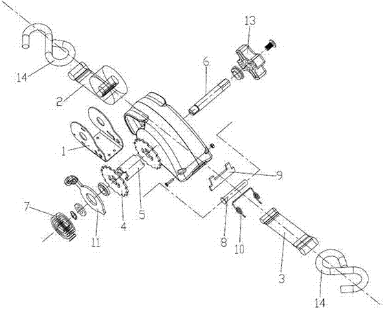
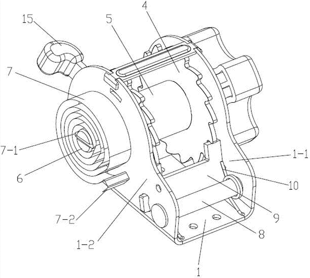
[0031] Such as Figure 1-7 As shown, an automatic take-up tensioning machine provided in this embodiment includes a base 1 with a groove 1-1 shape in cross section, a long webbing 2 and a short webbing 3, in the recess of the base 1 The slot 1-1 is provided with a ratchet wheel 4 which is sleeved on each end of both sides, and a shaft sleeve 5 with an opening 5-1 in the axial direction. The shaft sleeve 5 is hinged to the On a pair of side wall parts 1-2 of base 1, one side of base 1 is provided with coil spring 7, and one side end of rotating shaft 6 passes through its corresponding side wall part 1-2, and with coil spring The inner end 7-1 of 7 is connected, and a fixed shaft 8 arranged parallel to it is arranged on one radial side of the shaft sleeve 5, and the ends on both sides of the fixed shaft 8 extend to their corresponding side wall parts respectively. 1-2, a ratchet 9 hinged to a pair of side wall parts 1-2 of the base 1 is provided between the sleeve 5 and the fix...

Embodiment 2

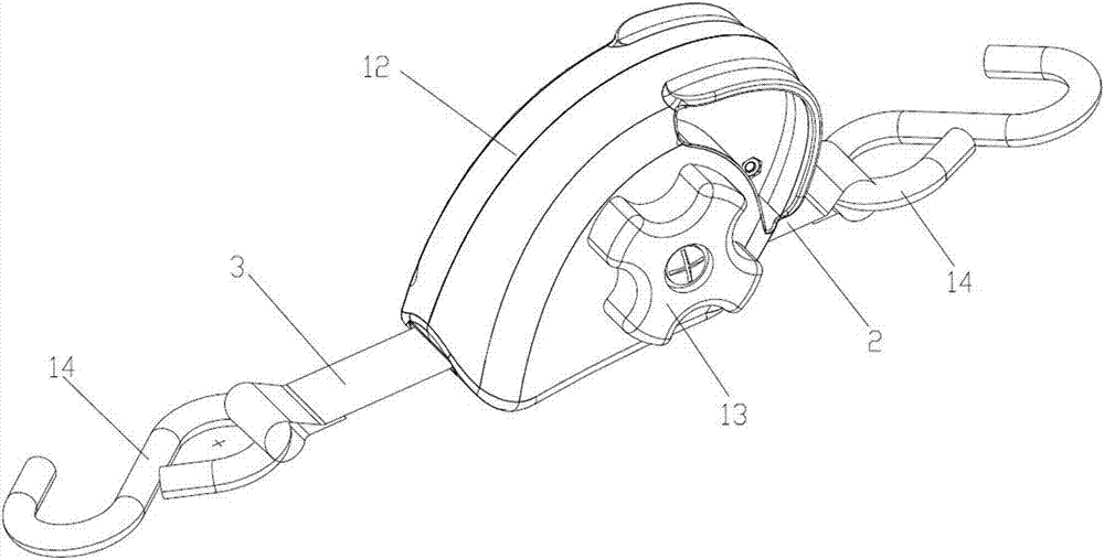
[0037] A kind of automatic take-up tensioning machine provided in this embodiment, its general structure is consistent with embodiment 1, as Figure 8 As shown, but the protective case 12 in this embodiment is mainly composed of three parts: the left half case 12-3, the right half case 12-4 and the coil spring cover 12-5, and the coil spring 7 is located in the coil spring cover 12 -5, and the coil spring cover 12-5 is fixed on the side wall part 11-2 of the base 1 on the corresponding side of the coil spring 7, after the left half shell 12-3 and the right half shell 12-4 are combined and fixed An accommodating chamber for sealing the base 1, the coil spring 7 and the coil spring cover 12-5 is formed.

[0038] For the above-mentioned automatic take-up and tensioning machine, considering that the coil spring 7 is a vulnerable part, and once damaged, it will directly affect the automatic take-up function of the automatic take-up and tensioning machine, so a coil spring is added ...

Embodiment 3

[0040] A kind of automatic take-up tensioning machine provided in this embodiment, its general structure is consistent with embodiment 2, as Figure 9 with Figure 10 shown, but one side of the lock plate 11 in this embodiment is provided with the second protruding part 11-3 for driving the ratchet 9 to compress a pair of ratchet wheels 4 when the lock plate 11 rotates, the first protrusion The part 11-1 is located below the second raised part 11-3, and a gap 11-4 is formed between the first raised part 11-1 and the second raised part 11-3, and there is no external force Under the influence of the torsion spring 10, the ratchet 9 is always snapped into the notch 11-4.

[0041] The above-mentioned lock plate 11 can promote the ratchet 9 engaged on a pair of ratchet wheels 4 to disengage from the ratchet wheel 4, and at the same time lift the handle portion 11-2 of the lock plate 11, and the second raised portion 11-3 of the lock plate 11 counterclockwise direction, the lock p...


PUM


Abstract

The invention discloses a tensioning machine capable of withdrawing tapes automatically. A fixing shaft and a shaft sleeve are arranged in a groove in a base, wherein the ends of the two sides of the shaft sleeve are each sleeved with a ratchet wheel, and the shaft sleeve can rotate around the shaft. A coil spring is arranged at one side of the base. The end of one side of a rotating shaft penetrates a side wall part corresponding to the rotating shaft and is connected with the end of one side of the coil spring. A pawl is arranged between the shaft sleeve and the fixing shaft, wherein the pawl is hinged to the pair of side wall parts of the base. The fixing shaft is provided with a torsional spring, wherein the torsional spring always drives the pawl to be engaged with the pair of ratchet wheels without being influenced by any external acting force. A locking plate is arranged between the ratchet wheel at any side and the side wall part corresponding to the ratchet wheel, wherein each locking plate is movably connected to the rotating shaft in a sleeving manner. A first protruding part is arranged at one side of each locking plate, wherein each first protruding part is used for driving the pawl to break away from the pair of ratchet wheels when the corresponding locking plate rotates. A protective shell used for sealing the base and the coil spring is further arranged outside the base. The end of the other side of the coil spring is fixed to the protective shell. By means of the tensioning machine, the technical effect that the service life of the tensioning machine capable of withdrawing the tapes automatically is prolonged is achieved; and the tensioning machine has the beneficial effect of being long in service life.

Description

technical field [0001] The invention relates to a tensioning machine, in particular to an automatic belt tensioning machine. Background technique [0002] Most of the tensioning machines currently on the market do not have the function of automatically retrieving the webbing. After unloading the goods, the operator has to spend a lot of time sorting and retrieving the webbing. [0003] In view of the above situation, the published Chinese invention patent document No. 200610050653.6 provides an automatic take-up tensioning machine, which includes a handle and a casing that are articulated through the main shaft, and the handle and the casing are respectively provided with large, A small baffle assembly, wherein the small baffle assembly includes a small baffle and a pressure spring, and the main shaft is provided with a take-up reel with ratchets at both ends and a take-up device for retrieving the webbing through a scroll spring The rear shaft of the casing is provided wit...

Claims


Application Information

Patent Timeline
IPC IPC(8): B65B13/22
CPCB65B13/22
Inventor 李成都李建标邵波
Owner 宁波希赫机械有限公司
Why Eureka
Try Eureka