

Lead seal feeding line-up mechanism for ammeter lead seal machine
A technology of queuing mechanism and sealing machine, which is applied in the direction of conveyor objects, transportation and packaging, etc., can solve the problems of inconvenient filling of lead seals, inconvenient installation of lead seals, and inability to ensure the direction of queuing and transfer of lead seals.
- Summary
- Abstract
- Description
- Claims
- Application Information
AI Technical Summary
Problems solved by technology
Method used
Image

Examples
Embodiment 1
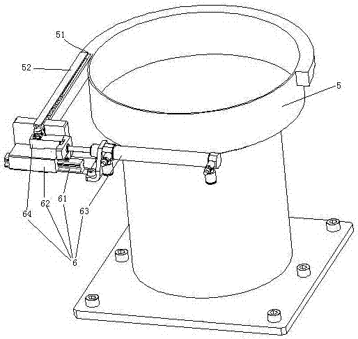
[0027] Embodiment one, see figure 1 , a lead seal feeding queuing mechanism for an electric meter lead sealing machine, including a vibrating plate 5 and a lead seal transfer mechanism 6 one by one.
[0028] The vibration plate 5 is provided with a material outlet 51 . The upper end of the material outlet 51 and the queuing chute 52 is butted together.
[0029] The lead seal transfer mechanism 6 is located at the lower end of the queuing chute 52 one by one. The transfer mechanism 6 for lead seals one by one includes a slide rail 61 , a slide block 62 and a driving cylinder 63 . The slide rail 61 extends along a direction perpendicular to the extending direction of the queuing chute. The slider 62 is slidably connected to the slide rail 61 . The driving cylinder 63 is used to drive the slider 62 to slide on the slide rail 61 . The slider 62 is provided with a raised bar 64 .
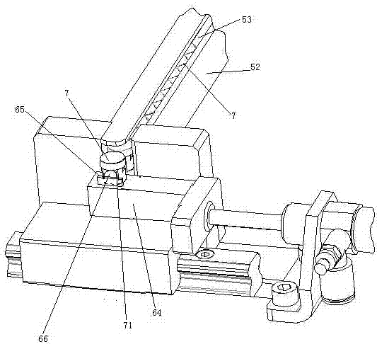
[0030] see figure 2 , The bottom wall of the queuing chute 52 is provided with a guide bar 5...
Embodiment 2
[0032] Embodiment two, the difference with embodiment one is:
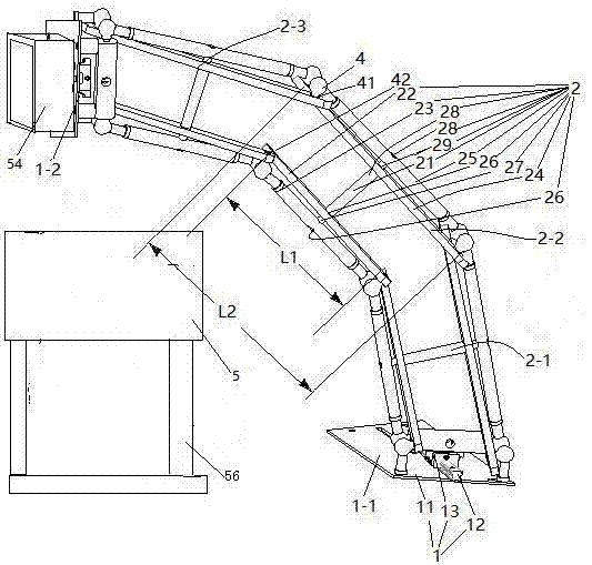
[0033] see image 3 , the vibrating plate 5 is supported by the supporting feet 56 . The vibrating plate 5 is provided with a lead seal feeding mechanism. The lead seal feeding mechanism includes a connecting seat assembly 1 and an arm 2.
[0034] There are two connecting seat assemblies 1. The two connecting seat assemblies 1 are respectively the first connecting seat assembly 1-1 and the last connecting seat assembly 1-2. Both the first connecting seat assembly 1-1 and the last connecting seat assembly 1-2 include a fixed seat 11, a slide rail 12 arranged on the fixed seat and a movable seat 13 slidably connected to the slide rail. The first connecting seat assembly 1-1 also includes a driving mechanism for driving the movable seat to slide on the slide rail (the driving mechanism is not shown in the figure), and the driving mechanism is an air cylinder. The first connecting seat assembly 1 - 1 is installed...
Embodiment 3
[0041] Embodiment three, the difference with embodiment two is:
[0042] see Figure 4 , the driving mechanism 3 provided on the first connecting seat assembly 1 includes a screw rod 32 and a driving motor 33 . One end of the screw rod 32 is threaded on the movable seat 13, and the other end is fixed together with the power output shaft 331 of the driving motor through a connector. A bearing seat 31 supporting the screw rod 32 is also provided on the fixing seat 11 . The connecting seat assembly 1 is also provided with a filler nozzle 9 for filling oil toward the slide bar 12 . During use, the screw mandrel 32 is driven to rotate by the driving motor 33 , and the screw mandrel 32 drives the movable seat 13 to slide on the slide rail 12 .
[0043] see Figure 5 , The filler nozzle 9 includes a filler nozzle body 91 and a filter plate 92 . The fuel nozzle body 91 is a cylindrical structure extending in the vertical direction. A flow channel 911 is provided in the fuel nozz...
PUM
 Abstract
Description
Claims
Application Information