Electric meter lead sealing machine lead seal feeding queuing mechanism
A technology of queuing mechanism and lead sealing machine, which is applied in the direction of conveyor objects, transportation and packaging, etc., which can solve the problems of inconvenient installation of lead seals, inability to guarantee the direction of transfer of lead seals in line, and inconvenience of pouring lead seals, etc.
- Summary
- Abstract
- Description
- Claims
- Application Information
AI Technical Summary
Problems solved by technology
Method used
Image
Examples
Embodiment 1
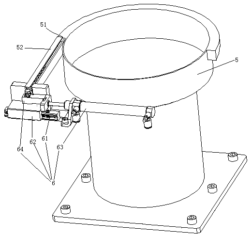
[0027] Example 1, see figure 1 , A lead seal feeding queuing mechanism of an electric meter lead sealing machine includes a vibrating plate 5 and a lead seal transfer mechanism 6 one by one.
[0028] The vibration plate 5 is provided with a material outlet 51. The material outlet 51 is butted with the upper end of the queuing chute 52.
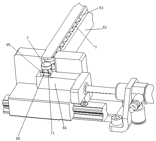
[0029] The lead seal transfer mechanism 6 is located at the lower end of the queuing chute 52. The lead seal transfer mechanism 6 includes a sliding rail 61, a sliding block 62 and a driving cylinder 63. The slide rail 61 extends perpendicular to the extension direction of the queue chute. The sliding block 62 is slidably connected to the sliding rail 61. The driving cylinder 63 is used to drive the slider 62 to slide on the sliding rail 61. A convex strip 64 is provided on the sliding block 62.
[0030] See figure 2 , The bottom wall of the queuing chute 52 is provided with a guide bar 53. The guide bar 53 extends along the extension directi...
Embodiment 2
[0032] The second embodiment is different from the first embodiment:
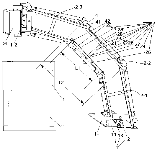
[0033] See image 3 , The vibration plate 5 is supported by the supporting feet 56. A lead sealing feeding mechanism is provided beside the vibration plate 5. The lead seal feeding mechanism includes a connecting seat assembly 1 and an arm 2.
[0034] There are two connecting seat assemblies 1. The two connecting seat assemblies 1 are the first connecting seat assembly 1-1 and the last connecting seat assembly 1-2, respectively. Both the first section connecting seat assembly 1-1 and the last section connecting seat assembly 1-2 include a fixed seat 11, a slide rail 12 arranged on the fixed seat, and a movable seat 13 slidably connected to the slide rail. The first section of the connecting seat assembly 1-1 also includes a driving mechanism that drives the movable seat to slide on the slide rail (the driving mechanism is not shown in the figure), and the driving mechanism is an air cylinder. The first-stage...
Embodiment 3
[0041] The third embodiment is different from the second embodiment:
[0042] See Figure 4 , The driving mechanism 3 provided on the first section of the connecting seat assembly 1 includes a screw rod 32 and a driving motor 33. One end of the screw rod 32 is threaded through the movable seat 13, and the other end is fixed with the power output shaft 331 of the driving motor through a connector. The fixing seat 11 is also provided with a bearing seat 31 supporting the screw rod 32. The connecting seat assembly 1 is also provided with an oil filling nozzle 9 for filling oil toward the sliding rod 12. When in use, the drive motor 33 drives the screw rod 32 to rotate, and the screw rod 32 drives the movable seat 13 to slide on the slide rail 12.
[0043] See Figure 5 , The fueling nozzle 9 includes a fueling nozzle body 91 and a filter plate 92. The fuel nozzle body 91 has a columnar structure extending in the up and down direction. A flow channel 911 is provided in the fuel noz...
PUM
 Abstract
Description
Claims
Application Information
 - R&D
- Intellectual Property
- Life Sciences
- Materials
- Tech Scout
- Unparalleled Data Quality
- Higher Quality Content
- 60% Fewer Hallucinations
Browse by: Latest US Patents, China's latest patents, Technical Efficacy Thesaurus, Application Domain, Technology Topic, Popular Technical Reports.
© 2025 PatSnap. All rights reserved.Legal|Privacy policy|Modern Slavery Act Transparency Statement|Sitemap|About US| Contact US: help@patsnap.com


