

Process for producing glass substrate, and glass substrate
A technology for glass substrates and manufacturing methods, applied in glass manufacturing equipment, manufacturing tools, glass cutting devices, etc., can solve problems such as defective products, position changes of anti-glare areas and non-glare areas, and achieve excellent productivity. Effect
- Summary
- Abstract
- Description
- Claims
- Application Information
AI Technical Summary
Problems solved by technology
Method used
Image

Examples
no. 1 approach
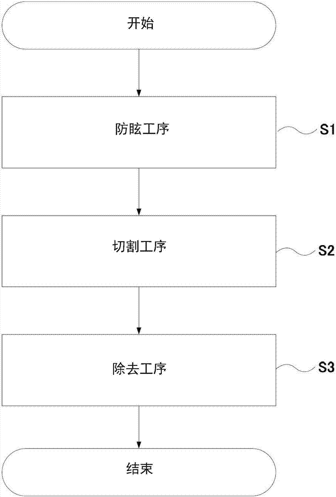
[0032] figure 1 It is a flowchart which schematically shows the manufacturing method of the glass substrate which concerns on 1st Embodiment of this invention. refer to figure 1 The manufacturing method of the glass substrate which concerns on 1st Embodiment of this invention is briefly demonstrated.
[0033] Such as figure 1 As shown, the method for manufacturing a glass substrate according to the first embodiment of the present invention includes a step of forming an anti-glare region (anti-glare step) S1 on at least one main surface of a glass plate, and a step of cutting the glass plate (cutting step) S2. , and a step of removing a part of the anti-glare region (removing step) S3.
[0034] S1 is a step of forming an anti-glare region on at least one main surface. The processing method is not particularly limited, and a method of surface-treating the main surface of the glass plate to form desired unevenness can be used. In the glass substrate of this embodiment, the an...
no. 2 approach
[0067] Figure 7 It is a flowchart which schematically shows the manufacturing method of the glass substrate of 2nd Embodiment of this invention. refer to Figure 7 The manufacturing method of the glass substrate which concerns on 2nd Embodiment of this invention is briefly demonstrated.
[0068] Such as Figure 7 As shown, the method for manufacturing a glass substrate according to the second embodiment of the present invention includes a step of forming an anti-glare region (anti-glare step) S1 on at least one main surface of a glass plate, and a step of removing a part of the anti-glare region ( Removal process) S2, and the process of cutting a glass plate (cutting process) S3.
[0069] The difference between the second embodiment and the first embodiment is that the removal step is performed before the cutting step. Other than that, it is the same as the above-mentioned first embodiment, and thus detailed description thereof will be omitted. As shown in the first embo...
Embodiment
[0071]Examples of the present invention are shown below. Examples 1 to 3 and 15 are examples, and examples 4 to 14 are comparative examples. Examples 1 to 12 used examples in which a silica-based anti-glare film mainly composed of silica was provided on the main surface of a glass plate, and examples 13 to 15 used a glass plate in which unevenness was formed on the surface of the glass plate itself by frost treatment. example. Polishing abrasive grain is white aluminum oxide polishing material (WA) in example 1~4,8~10,13,14, is diamond in example 5 and 12, is cerium oxide in example 6, in example 1,11 15 is green silicon carbide (GC).
[0072] The bonding material of the polishing stone was a metal bonding material in Examples 5 and 12, and a resin bonding material in other examples, but only in Example 1 was a resin bonding material having a lower modulus of elasticity than the other examples. The moving speed of the polishing grindstone was 2500 mm / minute in all examples,...
PUM
| Property | Measurement | Unit |
|---|---|---|
| hazing | aaaaa | aaaaa |
| hazing | aaaaa | aaaaa |
| particle diameter | aaaaa | aaaaa |
Abstract
Description
Claims
Application Information