
Drainage structure used for historic building gallery bridge and construction method thereof

A drainage structure and ancient building technology, which is applied in the direction of building structure, building, roof drainage, etc., can solve the problems of falling rainwater and affecting the function of bridges to avoid wind and rain, so as to increase the drainage of rainwater, facilitate docking, and improve stability Effect

Active Publication Date: 2017-06-27
ZHEJIANG UNIV OF WATER RESOURCES & ELECTRIC POWER
View PDF11 Cites 4 Cited by
  • Summary
  • Abstract
  • Description
  • Claims
  • Application Information

AI Technical Summary

Problems solved by technology

At present, the drainage of the covered bridge of ancient buildings mainly depends on the direct drainage of the roof of the covered bridge. When encountering strong wind and heavy rain, the discharged rainwater will fall into the inside of the covered bridge, which will affect the function of the covered bridge as a shelter from wind and rain.

Method used


Image

  • Drainage structure used for historic building gallery bridge and construction method thereof
  • Drainage structure used for historic building gallery bridge and construction method thereof
  • Drainage structure used for historic building gallery bridge and construction method thereof

Examples


Embodiment Construction

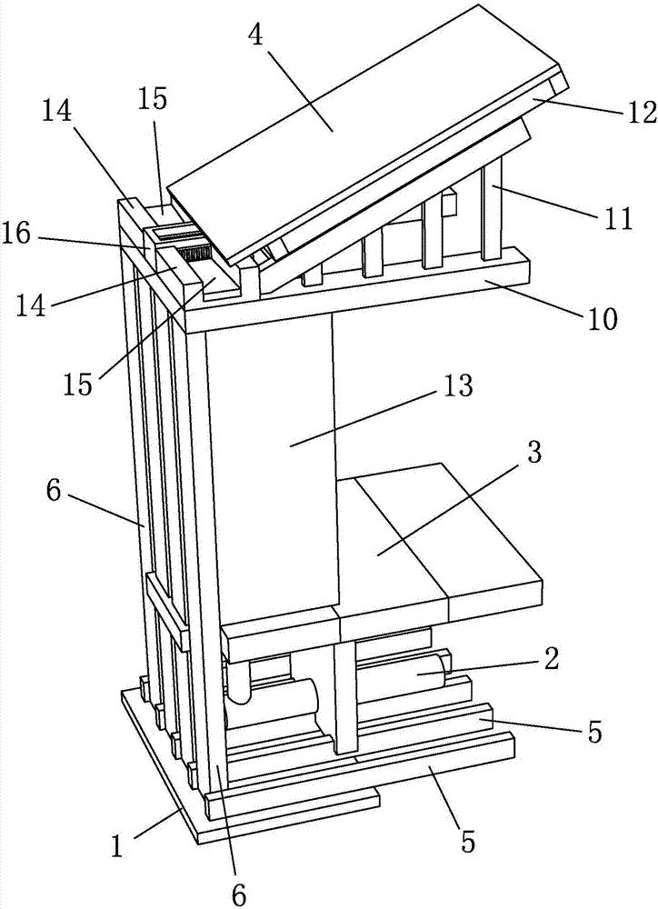
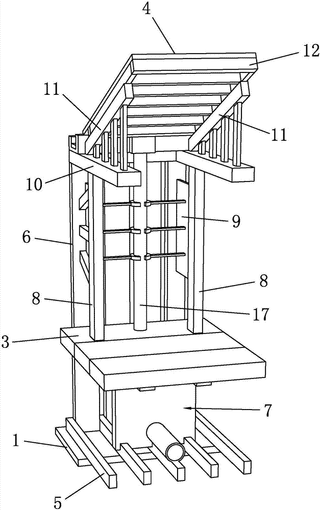
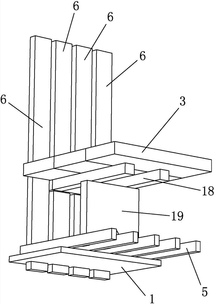
[0031] Such as Figure 1 to Figure 7 As shown, it is a drainage structure for ancient building bridges in the present invention, including embedded boards 1 , drainage pipes 2 , bridge floors 3 and bridge roofs 4 .

[0032] The top surface of the embedded board 1 is provided with a partition plate 5 and a vertical bar 6, and the bottoms of the vertical bar 6 are respectively fixed between two adjacent partition plates 5. A support structure 7 is provided on the vertical bar 6 distributed in the middle, and the support structure 7 is supported between the bridge floor 3 and the partition plate 5 , and the drainage pipe 2 is arranged in the support structure 7 . The support structure 7 includes a metal cross bar 18 and a metal plate 19, the metal cross bar 18 and the metal plate 19 are welded and fixed, the ends of the metal cross bar 18 are arranged on the vertical bar 6, the metal cross bar 18 supports the bridge floor 3, and the metal plate 19 is vertically fixed on the part...


PUM


Abstract

The invention discloses a drainage structure used for a historic building gallery bridge and a construction method thereof. The structure comprises a pre-buried plate, drainage pipes, gallery bridge floors and a gallery bridge roof. Supporting rods are arranged on the gallery bridge floors. Roof supports are arranged on the top of the supporting rods. Two drainage ditches are arranged on the tops of the roof supports. Flow guiding faces are arranged in the drainage ditches. A water collecting tank is arranged between the two drainage ditches. Water inlets are formed in the two sides of the water collecting tank. A rainwater pipe is arranged at the bottom of the water collecting tank and connected with the drainage pipes. The construction method comprises the steps that (a), a foundation structure of the historic building gallery bridge is built; (b) the drainage pipes are laid; (c), the gallery bridge roof and a historic building overall roof structure are connected in a butt joint mode; (d), a drainage system is arranged; and (e), the outer sides of the supporting rods are covered with decorative face plates. The rainwater drainage amount of the gallery bridge can be increased, and the situation that drained rainwater drifts down the interior of the gallery bridge is avoided, so that the effect of wind and rain sheltering is achieved.

Description

technical field [0001] The invention belongs to the technical field of drainage of corridor bridges of ancient buildings, and in particular relates to a drainage structure for corridor bridges of ancient buildings and a construction method thereof. Background technique [0002] Ancient Chinese buildings are mainly wooden frame structures, that is, wooden columns and beams are used to form the frame of the house. The weight of the roof and eaves is transmitted to the columns through the beam frame. [0003] Covered bridges, also known as Hongqiao, centipede bridges, etc., are bridges with a roof, which can protect the bridge, and at the same time provide shade and shelter, and provide people with rest, communication, and gathering functions. There are mainly wooden arched bridges, stone arched bridges, wooden flat covered bridges, wind and rain bridges, pavilion bridges and so on. [0004] There are various forms and styles of ancient building covered bridges across the coun...

Claims


Application Information

Patent Timeline
IPC IPC(8): E04D13/04E04D13/064E04D13/08E01D19/08
CPCE01D19/086E04D13/04E04D13/0481E04D13/064E04D13/08E04D2013/084
Inventor 刘学应杜赛永徐国梁毛琼晶
Owner ZHEJIANG UNIV OF WATER RESOURCES & ELECTRIC POWER
Learn More