Sensor calibration method for optical remote sensing satellite multi-CCD multi-camera unified processing

An optical remote sensing and multi-camera technology, applied in the direction of instruments, photogrammetry/video metrology, measuring devices, etc., can solve problems such as splicing errors, inability to eliminate the parallax of two cameras, and split the relationship between sensors, so as to improve the use efficiency Effect

Active Publication Date: 2017-06-27
CHINA CENT FOR RESOURCES SATELLITE DATA & APPL
View PDF5 Cites 17 Cited by
  • Summary
  • Abstract
  • Description
  • Claims
  • Application Information

AI Technical Summary

Problems solved by technology

[0014] However, the above methods all process different cameras on the platform separately, which splits the relationship between sensors and requires multiple resampling, resulting in reduced user efficiency and the inability to eliminate the parallax between the two cameras, resulting in a certain stitching error

Method used


Image

  • Sensor calibration method for optical remote sensing satellite multi-CCD multi-camera unified processing
  • Sensor calibration method for optical remote sensing satellite multi-CCD multi-camera unified processing
  • Sensor calibration method for optical remote sensing satellite multi-CCD multi-camera unified processing

Examples


Embodiment Construction

[0045] The present invention will be described in detail below with reference to the drawings and examples.

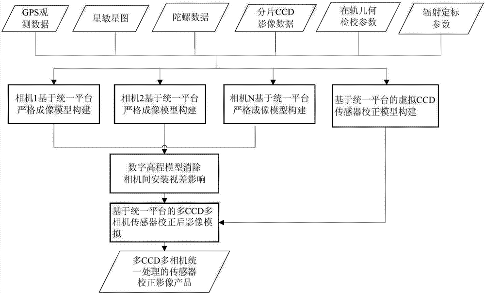
[0046] An optical remote sensing satellite multi-CCD multi-camera unified processing sensor calibration method, the steps are as follows:

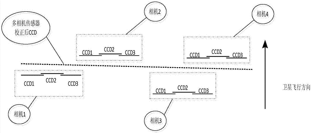
[0047] The first step is to construct a virtual CCD linear array based on the installation position of each CCD linear array of multiple cameras on the optical remote sensing satellite platform along the orbital direction, and install the virtual CCD linear array on the centerline of the multiple cameras along the orbital direction;

[0048] (1) Features and advantages of sensor calibration image based on a unified platform

[0049] a. The vertical orbit direction is ideal, distortion-free center projection imaging, and the size of each CCD detector is the same;

[0050] b. The integration time along the orbit is the same, and there is no integration time jump; there is no geometric distortion along the orbit;

[0051] c. No radiation differe...


PUM


Abstract

The invention relates to a sensor calibration method for optical remote sensing satellite multi-CCD multi-camera unified processing. The sensor calibration method comprises the following steps: firstly taking mounting positions of CCD linear arrays of multiple cameras on an optical remote sensing satellite platform along the direction of a track as benchmark, constructing a virtual CCD linear array, and mounting the virtual CCD linear array on a center line of multiple cameras along the direction of the track; secondly, establishing a strict imaging model of a unified platform; thirdly, constructing a strict imaging model of each CCD; fourthly, for each image point on the virtual CCD linear array, according to direct transformation of the strict imaging model of the unified platform, calculating plane coordinates of a ground point of the image point, and assigning a value to the average elevation of the ground point, so that geographic coordinates of the ground point are obtained; fifthly, according to the strict imaging model of each CCD and the geographic coordinates, calculated in the step four, of the ground point, calculating image point coordinates of the image point by adopting strict imaging model inverse transformation, and assigning a value to a virtual CCD image point; and sixthly, repeating the steps four and five until processing of all the image elements on a virtual CCD is completed.

Description

Technical field [0001] The invention belongs to the field of optical remote sensing satellite data processing and is suitable for the field of aerial photogrammetry. Background technique [0002] With the advancement and development of remote sensing and satellite technology, users have increasingly higher requirements for the geometric resolution, geometric quality, and width of high-resolution satellite images. [0003] Due to the limitation of CCD devices, domestic high-resolution remote sensing satellites will use multiple CCDs and multiple cameras to image together in order to meet the user's requirements for width at present and for a period of time in the future. Each camera is the center projection image. At the same time, in the sub-meter remote sensing camera, the load side is to reduce the impact of the edge MTF drop to ensure the image clarity; in the design of the focal plane, it began to learn from the advanced experience of foreign countries to adopt the arc design, ...

Claims


Application Information

Patent Timeline
Patent Type & Authority Applications(China)
IPC IPC(8): G01C25/00G01C11/00
CPCG01C11/00G01C25/00
Inventor 王冰冰龙小祥李庆鹏喻文勇崔林秦敬芳
Owner CHINA CENT FOR RESOURCES SATELLITE DATA & APPL
Why Eureka
Try Eureka