Imaging lens and imaging apparatus

A camera lens and lens technology, applied in optical observation devices, image communication, transportation, packaging, etc., can solve the problems of small F value, inability to obtain high resolution, and many residual aberrations, etc., and achieve the effect of small F value

Active Publication Date: 2017-06-27
TIANJIN OFILM OPTO ELECTRONICS CO LTD
View PDF9 Cites 8 Cited by
  • Summary
  • Abstract
  • Description
  • Claims
  • Application Information

AI Technical Summary

Problems solved by technology

[0011] However, when the lens system described in Patent Document 1 is used in a vehicle-mounted camera or a surveillance camera, it cannot be said that the F value is small, and there are many residual aberrations, so high resolution cannot be obtained up to the periphery of the imaging area.
In the 6-element lens system described in Patent Documents 2 and 3, correction of chromatic aberration and coma aberration is insufficient, and high resolution cannot be obtained up to the periphery of the imaging area.

Method used


Image

  • Imaging lens and imaging apparatus
  • Imaging lens and imaging apparatus
  • Imaging lens and imaging apparatus

Examples


Embodiment 1

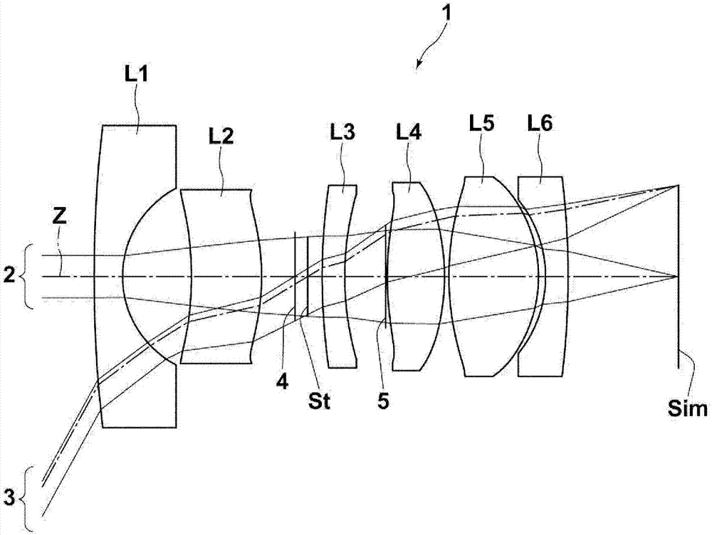
[0182] figure 2 A cross-sectional view of the imaging lens of Example 1 is shown. The imaging lens of Example 1 is composed of six lenses, namely the first lens L1 to the sixth lens L6. exist figure 2 Among them, the left side is the object side, and the right side is the image side, electrically showing the aperture stop St, the above-mentioned first light shielding member 4 , and the second light shielding member 5 . It should be noted, figure 2 The aperture stop St, the first light shielding member 4 , and the second light shielding member 5 shown do not necessarily represent sizes and shapes, but represent positions on the optical axis.

[0183] Table 1 shows basic lens data of the imaging lens of Example 1, and Table 2 shows aspheric coefficients. The column of Si in Table 1 shows the numbering of the faces of the constituent elements in such a manner that the object-side face of the most object-side constituent element is set as the first and increases sequentiall...

Embodiment 2

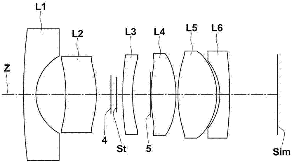
[0206] image 3 A cross-sectional view of the imaging lens of Example 2 is shown. Table 3 shows the basic lens data of the imaging lens of Embodiment 2, and Table 4 shows the aspheric coefficients, Figure 12 , Figure 21 Each aberration diagram in a state of focusing on an object at infinity is shown.

[0207] 【table 3】

[0208] Example 2

[0209] f=3.35, Bf=4.30, FNo.=2.27, 2ω=122.6°

[0210] Si Ri Di Ndj vdj *1 46.3783 1.0112 1.58313 59.38 *2 3.1881 2.5131 *3 -13.4465 2.5001 1.80610 40.93 *4 -8.0867 1.6700 5(St) ∞ 0.2499 6 63.9530 0.8632 1.92286 18.90 7 15.0562 1.6101 *8 10.5055 2.0399 1.80610 40.93 *9 -7.6909 0.1549 *10 10.4629 2.8474 1.61881 63.85 *11 -4.9605 0.2699 12 -4.2728 0.8000 1.92286 18.90 13 -25.9702 4.3020

[0211] 【Table 4】

[0212] Example 2

[0213] face number 1 2 3 4 KA 1.0015654E+00 9.80347...

Embodiment 3

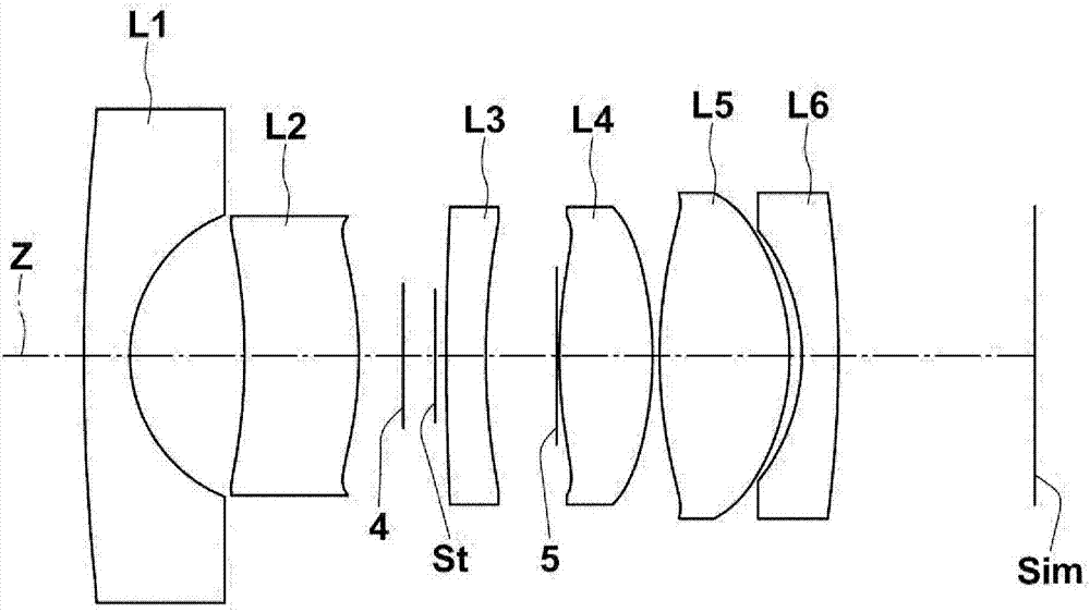
[0215] Figure 4 A cross-sectional view of the imaging lens of Example 3 is shown. Table 5 shows the basic lens data of the imaging lens of Embodiment 3, and Table 6 shows the aspheric coefficients, Figure 13 , Figure 22 Each aberration diagram in a state of focusing on an object at infinity is shown.

[0216] 【table 5】

[0217] Example 3

[0218] f=3.31, Bf=4.12, FNo.=2.26, 2ω=130.0°

[0219] Si Ri Di Ndj vdj 1 46.3786 1.0200 1.58313 59.38 2 3.2332 2.5830 *3 -16.2066 1.8749 1.80610 40.93 *4 -9.4864 1.7610 5(St) ∞ 0.2500 6 212.1128 0.8567 1.95906 17.47 7 20.7117 2.0115 *8 9.4219 2.0465 1.80610 40.93 *9 -9.1476 0.1549 10 9.2275 3.1492 1.61881 63.85 11 -5.0420 0.2840 12 -4.1226 0.7999 1.95906 17.47 13 -17.3321 4.1164

[0220] 【Table 6】

[0221] Example 3

[0222] face number 3 4 8 9 KA 4.9943054E+00 -3.2075243E...


PUM


Abstract

The present invention provides small F-measure, wide-angle and compact structure, from the center of the Ministry of the imaging area to the imaging regions of the periphery so far will be able to get a good image of the camera lens, and imaging apparatus equipped with the camera lens. The camera lens (1) in order from the object side substantially from the concave toward the image side of the negative first lens (L1), a positive second lens convex toward the image side (L2), a third negative lens concave toward the image side (L3), biconvex positive fourth lens shape (L4), positive the fifth lens is biconvex shape (L5), a sixth negative lens concave toward the object side (L6) formed. The imaging lens (1) satisfies the conditional formula relating to the radius of curvature (R3) of the object side of the second lens (L2) and the focal length (f) of the whole system (1): R3 / F < 0.

Description

technical field [0001] The present invention relates to an imaging lens suitable for a vehicle-mounted camera, a surveillance camera, a camera for a portable terminal, and the like, and an imaging device including the imaging lens. Background technique [0002] In recent years, in-vehicle cameras have been used to assist in the confirmation of blind spot areas such as the driver's side and rear, image recognition of the periphery of the vehicle, and the like. On the other hand, surveillance cameras are often used for the purpose of crime prevention, recording, and the like. Imaging lenses used in these cameras are required to have a compact structure and excellent performance. As an imaging lens satisfying such a request, for example, a lens system in which the number of lenses is set to six is ​​considered. The following Patent Documents 1 to 6 disclose lens systems having a six-element structure. [0003] prior art literature [0004] Patent Document 1: Japanese Patent...

Claims


Application Information

Patent Timeline
Patent Type & Authority Applications(China)
IPC IPC(8): G02B13/06G02B13/18G02B13/04
CPCG02B13/04G02B13/06G02B13/18G02B9/62G02B13/0045H04N23/90B60R1/081B60R1/12B60R11/04B60R2001/1253G02B27/0025H04N7/181
Inventor 森将生
Owner TIANJIN OFILM OPTO ELECTRONICS CO LTD
Why Eureka
Try Eureka