
Method and system for automatic wireless charging of unmanned aerial vehicle
A wireless charging and unmanned aerial vehicle technology, applied in the direction of finding the target control, etc., can solve the problems of inability to accurately align the wireless charging transmitting module and the wireless charging receiving module, reduce the efficiency of wireless charging, and the positioning accuracy is not high enough, so as to improve wireless charging. The effect of charging efficiency and drone endurance, narrowing the positioning range, and fast positioning speed
- Summary
- Abstract
- Description
- Claims
- Application Information
AI Technical Summary
Problems solved by technology
Method used
Image

Examples
Embodiment Construction
[0029] The present invention will be further described in conjunction with the accompanying drawings and specific embodiments.
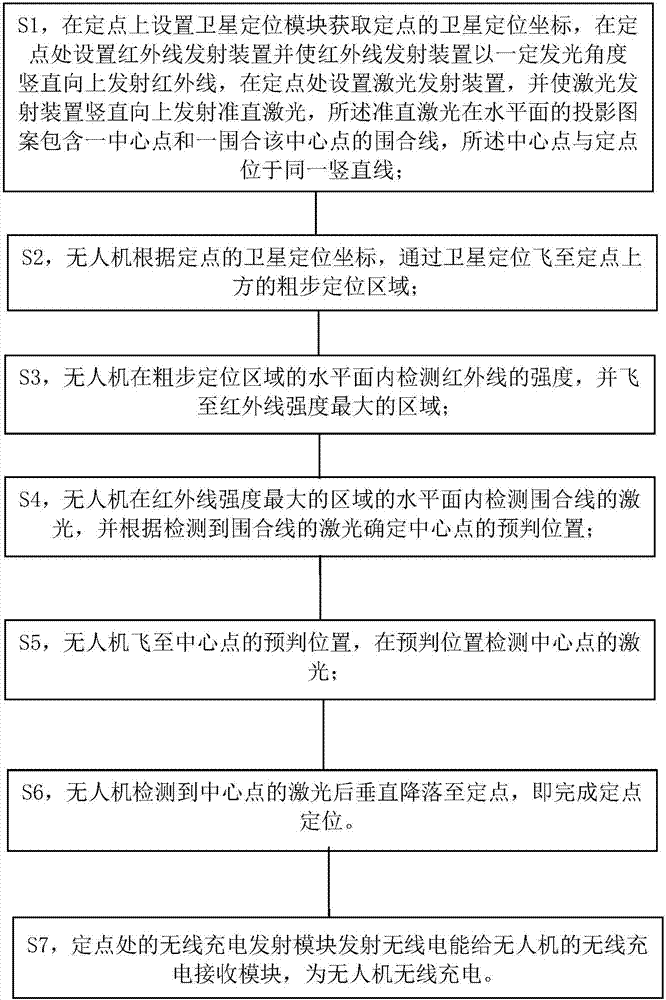
[0030] Such as Figure 1-3 Described, a kind of unmanned aerial vehicle automatic wireless charging method, comprises the steps:
[0031] S1, set the satellite positioning module on the fixed point B of the apron 1 to obtain the satellite positioning coordinates of the fixed point B. In this specific embodiment, the satellite positioning module is a GPS positioning module. Of course, in other embodiments, it can also be Beidou satellite positioning module, in some embodiments, if the apron is fixed, the GPS positioning module may not be provided, as long as the GPS positioning coordinates are determined when the apron is set.
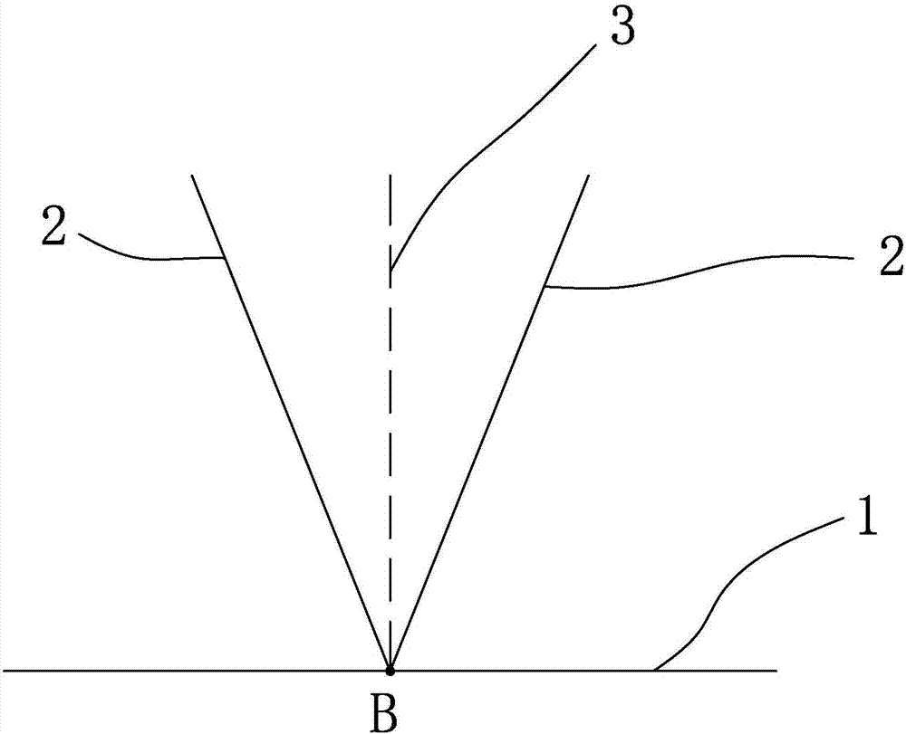
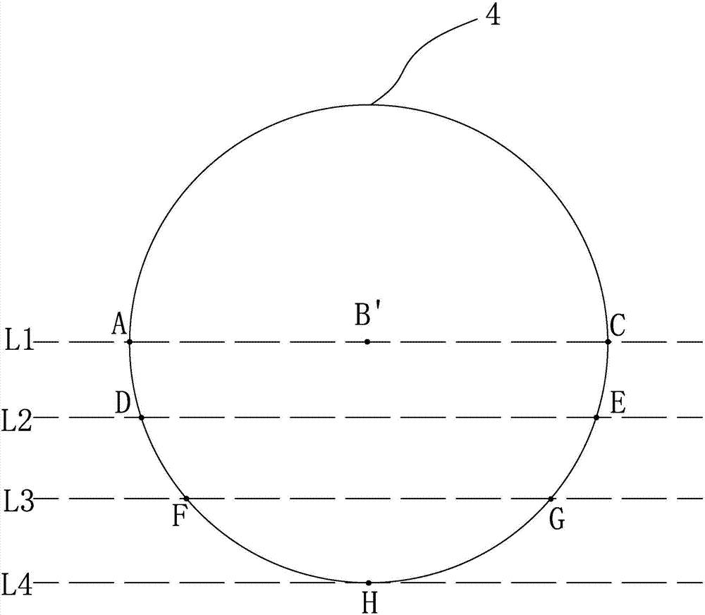
[0032] Set the infrared emitting device at the fixed point B and make the infrared emitting device emit infrared rays vertically upward at a certain light angle, specifically as figure 2 As shown, the normal axis 3 of the i...
PUM
 Abstract
Description
Claims
Application Information