
Synthesis method of planar array antenna and difference beam pattern based on hybrid algorithm

A planar array antenna, hybrid algorithm technology, used in antennas, complex mathematical operations, electrical components, etc.

Active Publication Date: 2017-06-27
JINLING INST OF TECH
View PDF3 Cites 20 Cited by
  • Summary
  • Abstract
  • Description
  • Claims
  • Application Information

AI Technical Summary

Problems solved by technology

[0003] In order to solve the above existing problems, the present invention provides a planar array antenna and difference beam pattern synthesis method based on a hybrid algorithm. The hybrid optimization method in the present invention avoids the inability of the traditional IFT algorithm to perfect the sum and all radiation performance of the difference beam and the QP algorithm. The shortcoming of a long calculation period when the unknown variable surges, effectively combines the iterative Fourier algorithm and the QP algorithm without parameter adjustment and strong robustness, fast calculation speed, and high precision, and finally realizes the simplification of the feed network, only through The current excitation and phase excitation changes of some array elements are used to realize the conversion between sum and difference beams. To achieve this purpose, the present invention provides a hybrid algorithm-based planar array antenna and difference beam pattern synthesis method, including the following steps:

Method used


Image

  • Synthesis method of planar array antenna and difference beam pattern based on hybrid algorithm
  • Synthesis method of planar array antenna and difference beam pattern based on hybrid algorithm
  • Synthesis method of planar array antenna and difference beam pattern based on hybrid algorithm

Examples


Embodiment Construction

[0068] Below in conjunction with accompanying drawing and specific embodiment the present invention is described in further detail:

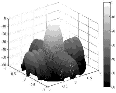
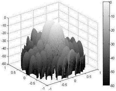
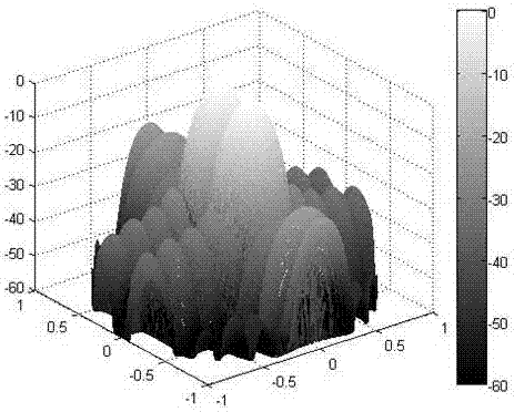
[0069] The invention provides a planar array antenna and difference beam pattern synthesis method based on a hybrid algorithm. The invention uses the MIFT method to calculate the excitation value of the shared unit corresponding to the sidelobe requirements of the sum and difference beams, and then uses the QP algorithm to calculate in parallel to obtain the satisfaction and difference The current excitation of the remaining units outside the shared unit corresponding to the radiation performance such as the maximum value of the sidelobe level of each beam, the slope of the zero point position of the difference beam, and the maximum directivity coefficient.

[0070] As an embodiment of the present invention, the present invention considers a 25×25 planar array antenna with an element spacing of 0.5λ. In order to simplify the feed network, 20% or ...


PUM


Abstract

Disclosed is a planar array antenna and difference beam forming method, that is, under the premise of reducing the complexity of a feeder network, only the current excitation and phase excitation of some array elements are changed to realize the conversion between the sum and difference beams. The method includes the steps of using an improved iterative Fourier algorithm to derive unit current excitation values corresponding to sum and difference beam patterns satisfying performance requirements of the sidelobe level, 3dB beam width and the like, retaining the amplitude of the same excitation unit portion corresponding to the two beams, and then, using an improved quadratic programming algorithm to find an array element excitation value outside a common excitation unit set to satisfy respective performance requirements of the sum and difference beams, including the maximum value of the sidelobe level, the slope of a zero position of the difference beam, the directionality coefficient, and so forth. The method of the invention realizes the conversion between the sum and difference beams only by changing the current excitation and the phase excitation of some array elements under the premise that the complexity of the feeder network is reduced.

Description

technical field [0001] The invention relates to the technical fields of wireless communication and signal processing, in particular to a hybrid algorithm-based planar array antenna and a method for synthesizing a difference beam pattern. Background technique [0002] The comprehensive optimization method of planar antenna and difference beam antenna pattern is a technology that only changes the current excitation and phase excitation of some array elements to realize the conversion between sum and difference beams. In many practical applications, suppressing the sidelobe of the array pattern is a basic and very important issue. For a radar system using monopulse technology, it is necessary to suppress the sidelobe of the sum beam and the difference beam at the same time. Two forms of weighting are used on the elements, Taylor weighting for the sum beam and Bayliss weighting for the difference beam. However, for large-scale phased array radars with hundreds to thousands of ar...

Claims


Application Information

Patent Timeline
Patent Type & Authority Applications(China)
IPC IPC(8): H01Q25/02G06F17/14
CPCG06F17/14H01Q25/02
Inventor 田小敏杨忠司海飞
Owner JINLING INST OF TECH
Learn More