Ultrasonic transducer, ultrasonic array probe and ultrasonic imaging system
An ultrasonic transducer, ultrasonic array technology, applied in ultrasonic/sonic/infrasound image/data processing, ultrasonic/sonic/infrasonic diagnosis, sonic diagnosis, etc., can solve the high processing requirements of piezoelectric materials, manufacturing process and control The method is complicated and other problems, so as to achieve the effect of improving the imaging resolution and increasing the bandwidth.
- Summary
- Abstract
- Description
- Claims
- Application Information
AI Technical Summary
Problems solved by technology
Method used
Image

Examples
Embodiment 1
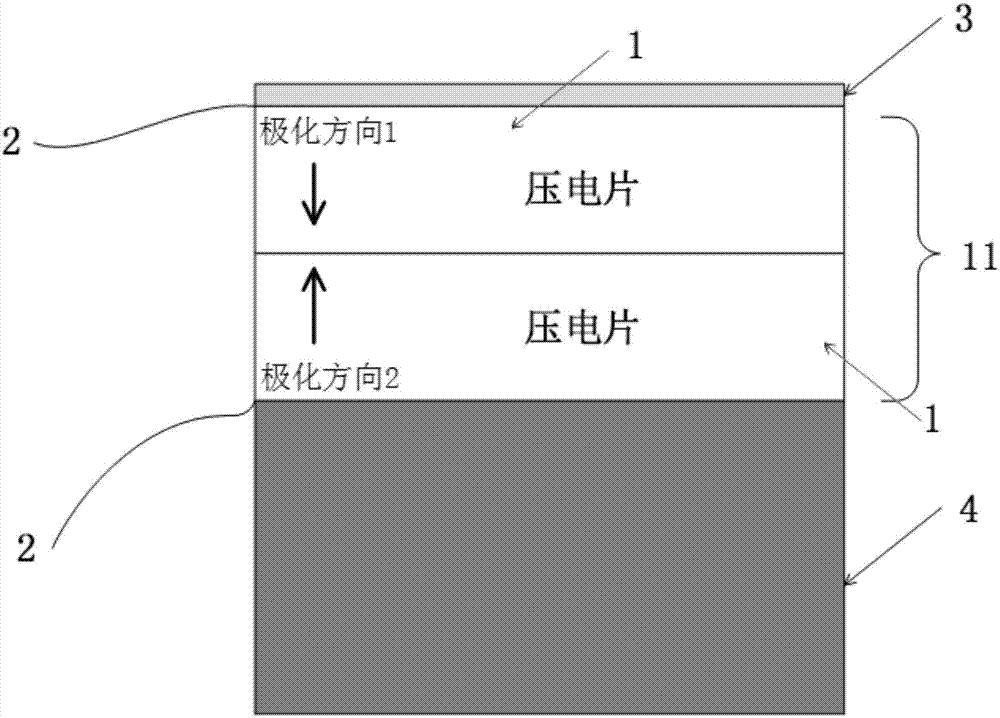
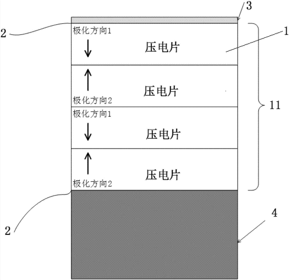
[0038] Such as figure 1 with 2 As shown, this embodiment provides an ultrasonic transducer, including: a piezoelectric sheet group, the piezoelectric sheet group includes at least two piezoelectric sheets 1 stacked along the thickness direction and the poles of two adjacent piezoelectric sheets 1 in the opposite direction.
[0039]In the ultrasonic transducer provided in this embodiment, by superimposing two or more piezoelectric sheets 1 with different polarization directions, the ultrasonic transducer has the reference frequency of each piezoelectric sheet 1 forming its working layer. There are also multiple synthetic resonant frequencies, and the difference from the traditional multi-layer superimposed ultrasonic transducer and the traditional reverse layer transducer is that when the thickness of each layer of piezoelectric sheet 1 is the same, the frequency at which the resonance occurs is no longer 2 Double the frequency but triple the frequency. Image 6 Shown is the...
Embodiment 2
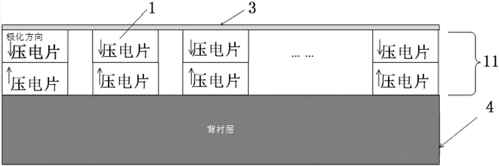
[0044] An embodiment of the present invention provides an ultrasonic array probe, which includes: a multi-element array formed by a plurality of ultrasonic transducers arranged in arrangement.
[0045] Such as image 3 As shown, the ultrasonic transducer includes at least two piezoelectric sheet groups, and one side surfaces of the at least two piezoelectric sheet groups are commonly connected by a conductive member. The ultrasonic transducer may include a plurality of piezoelectric sheet groups, and the plurality of piezoelectric sheet groups may form an array as ultrasonic array elements.
[0046] As an optional implementation mode, the ultrasonic transducers of this embodiment share a bottom or top piezoelectric sheet, and the corresponding top or bottom piezoelectric sheets are arranged separately, wherein the shared piezoelectric sheet can be used as a common ground terminal, The separately arranged piezoelectric sheets are respectively connected to the electrodes, so as...
Embodiment 3
[0051] Such as Figure 5 As shown, this embodiment provides an ultrasonic imaging system, including: any one of the ultrasonic transducers with reversed layer distribution provided in the above-mentioned embodiment 1, an ultrasonic transmitting circuit, an ultrasonic echo receiving circuit, and an ultrasonic echo receiving circuit. The wave is processed and converted into a processing circuit for images, and a transceiving switch (T / R Switch) for switching the ultrasonic transmitting circuit and the ultrasonic echo receiving circuit.
[0052] Specifically, the above-mentioned ultrasonic transducer forms an ultrasonic probe 21; the transceiving switch 22 is used to control the switching of the ultrasonic transmitting circuit and the ultrasonic echo receiving circuit; the ultrasonic transmitting circuit includes a pulse transmitter 23; the ultrasonic echo receiving circuit includes an echo Receiver 24; processing circuit includes IL (inversion layer, inversion layer) time gain c...
PUM
 Abstract
Description
Claims
Application Information
 - R&D Engineer
- R&D Manager
- IP Professional
- Industry Leading Data Capabilities
- Powerful AI technology
- Patent DNA Extraction
Browse by: Latest US Patents, China's latest patents, Technical Efficacy Thesaurus, Application Domain, Technology Topic.
© 2024 PatSnap. All rights reserved.Legal|Privacy policy|Modern Slavery Act Transparency Statement|Sitemap