Method and apparatus for adaptive transmission of sensor data with latency controls

a technology of sensor data and latency control, applied in electrical devices, network topologies, network traffic/resource management, etc., can solve the problems of limited and highly variable link bandwidth, high bandwidth consumption, and high bandwidth of wide area communication networks with wireless network segments, so as to minimize data latency and maximize available network bandwidth. , the effect of high bandwidth

Active Publication Date: 2010-11-04
STEVENS INSTITUTE OF TECHNOLOGY
View PDF24 Cites 243 Cited by
  • Summary
  • Abstract
  • Description
  • Claims
  • Application Information

AI Technical Summary

Benefits of technology

[0007]A method and apparatus to continuously transmit high bandwidth, real-time data, on a communications network is described. The described system enables a control computing device to dynamically adjust the throughput from a remote computing device to match the bandwidth of the communications network being used, so that data latency is minimized and the available network bandwidth is fully utilized. The system allows for the visualization of the instantaneous characteristics of the link and, if necessary, makes a tradeoff between the latency and resolution (throughput) of the data to help maintain the real-time nature of the system. Automated control strategies are implemented into the system to enable dynamic adjustments of the system throughput to minimize latency while maximizing data resolution.

Problems solved by technology

For all their advantages, however, wide area communication networks with wireless network segments typically have a few major limitations.
One typical limitation of wireless networks is their limited and highly variable link bandwidth.
Other limitations of wireless networks include their susceptibility to bandwidth losses due to various kinds of interference, their reduction in throughput performance due to attenuation of radio signals with distance and performance degradation due to attenuating objects in the signal path.
Additionally, the user of the ubiquitous Transmission Control Protocol (TCP), which is not optimized for use in wireless networks, is another factor that can reduce the available bandwidth of wireless networks.
While these limitations may not be of concern for applications with low bandwidth requirements and tolerance to high data latencies, it is often a problem for real-time applications.
In many real-time applications, the usefulness of the data decays rapidly with time.
Therefore, neither desired throughput nor latency can be guaranteed.

Method used


Image

  • Method and apparatus for adaptive transmission of sensor data with latency controls
  • Method and apparatus for adaptive transmission of sensor data with latency controls
  • Method and apparatus for adaptive transmission of sensor data with latency controls

Examples


example implementation

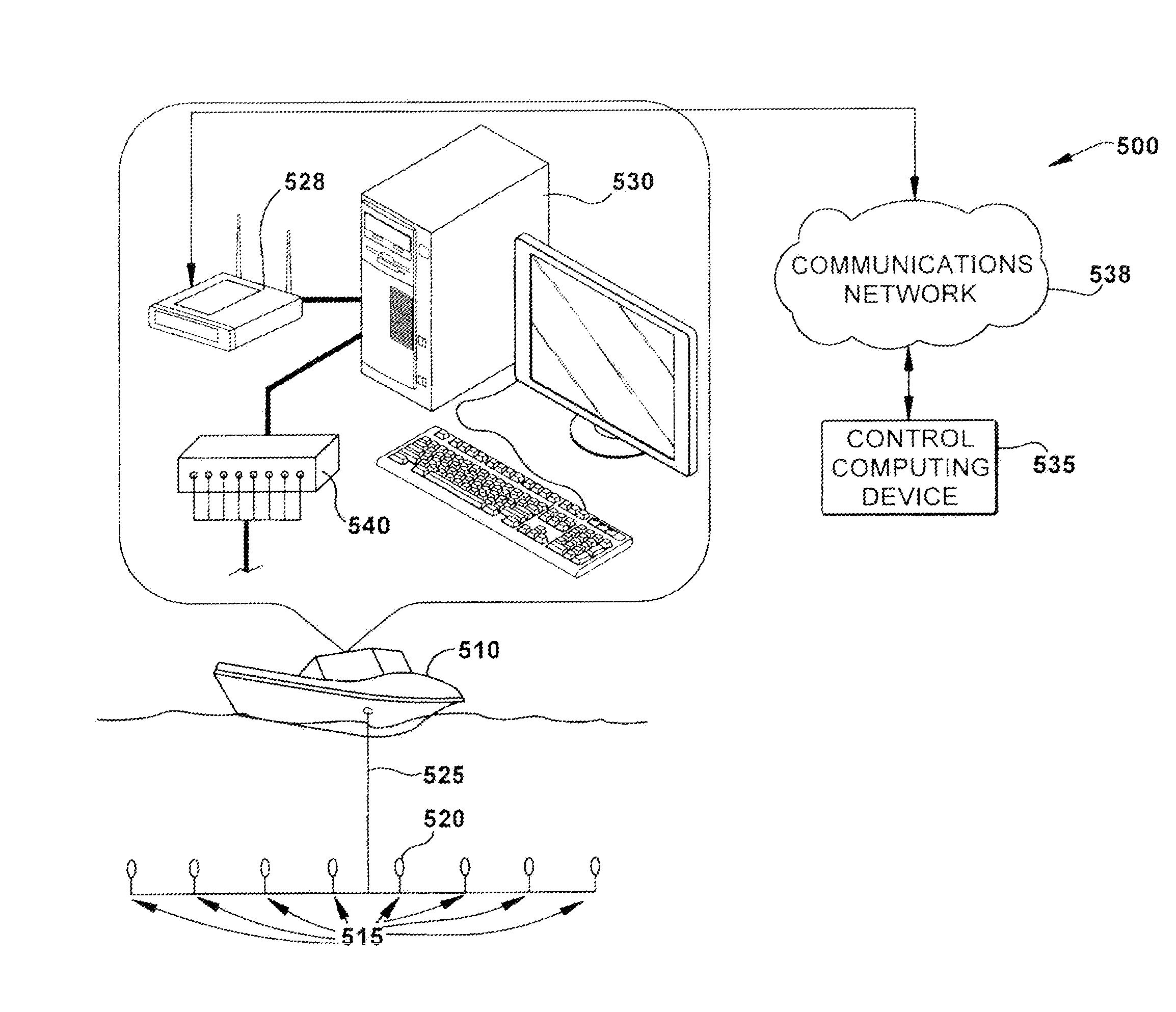
[0060]FIG. 5 shows a block diagram of an embodiment of an example system including a boat 510 connected to a plurality of (in this example, eight) hydrophones 515 (e.g., hydrophone 520) via a hydrophone cable 525. The hydrophones are situated at a remote offshore location. The hydrophones are used to pick up acoustic signals underwater. Similar to microphones, they work as sound to electricity transducers. In one embodiment, the hydrophones are placed a couple of hundred feet offshore and a wireless router 528 is used to transmit the data from the remote computing device 530 to the control computing device 535 over wireless network 538.

i) Remote Computing Device 530

[0061]In the boat example mentioned above, to obtain voltage data from the hydrophones 515, each hydrophone is connected to a hydrophone terminal box 540. In one embodiment, this terminal box 540 outputs the hydrophone voltage reading from the different input jacks to a data acquisition card connected to the remote comput...


PUM


Abstract

Disclosed is a method and apparatus to continuously transmit high bandwidth, real-time data, on a communications network (e.g., wired, wireless, and a combination of wired and wireless segments). A control computing device uses user or application requirements to dynamically adjust the throughput of the system to match the bandwidth of the communications network being used, so that data latency is minimized. An operator can visualize the instantaneous characteristic of the link and, if necessary, make a tradeoff between the latency and resolution of the data to help maintain the real-time nature of the system and better utilize the available network resources. Automated control strategies have also been implemented into the system to enable dynamic adjustments of the system throughput to minimize latency while maximizing data resolution. Several applications have been cited in which latency minimization techniques can be employed for enhanced dynamic performance.

Description

RELATED APPLICATIONS[0001]This application claims the benefit of U.S. Provisional Application Ser. No. 61 / 144,891, filed Jan. 15, 2009; U.S. Provisional Application Ser. No. 61 / 206,040, filed Jan. 23, 2009; and U.S. Provisional Application Ser. No. 61 / 147,413, filed Jan. 26, 2009, all of which are incorporated herein by reference in their entirety.STATEMENT REGARDING FEDERALLY SPONSORED RESEARCH[0002]Development of the subject matter disclosed herein was supported in part by US ARMY / ARDEC Grant No. W15QKN-05-D-0011 Task 31. The U.S. government may have certain rights in this application.FIELD OF THE INVENTION[0003]The disclosed subject matter relates to the field of sensor data acquisition, remotely operated robots, industrial machinery, sensor data processing and communications for remote system monitoring and control.BACKGROUND OF THE INVENTION[0004]Wide area communication networks, which contain both wired and wireless networks, are an attractive method of data transmission over ...

Claims


Application Information

Patent Timeline
Patent Type & Authority Applications(United States)
IPC IPC(8): H04W40/00
CPCH04W28/20H04W28/22H04L69/24H04L67/125H04W84/18
Inventor POCHIRAJU, KISHOREGEBRE, BIRUKMEN, HAO
Owner STEVENS INSTITUTE OF TECHNOLOGY
Why Eureka
Try Eureka