Spiral single-yarn piezoelectric spray dyeing device

A spiral, piezoelectric technology, applied in the field of yarn dyeing, can solve the problems of air pollution, easy generation of dust, uneven dyeing of yarn, etc., and achieve the effect of high degree of automation, reasonable structure design and high dyeing efficiency

Inactive Publication Date: 2017-06-30
WUHAN TEXTILE UNIV
View PDF8 Cites 13 Cited by
  • Summary
  • Abstract
  • Description
  • Claims
  • Application Information

AI Technical Summary

Problems solved by technology

Equipment using the dip dyeing method, including patents ZL201310550132.7, ZL201220183093.2 and ZL 201310551500.X, will face problems such as insufficient use of dye solution and waste, and one yarn can only be dyed in one color.
Existing equipment using spray dyeing, including ZL201420667869.7 and ZL200410028019.3, all use single-side spraying, which may easily cause uneven dyeing of yarns
At the same time, the nozzles of the existing spraying and dyeing equipment are prone to generate dust during high-speed operation, and due to the insufficient control of the spraying and dyeing dosage, it is easy to cause dye particles to float in the air, thereby polluting the air and affecting the quality of the yarn

Method used


Image

  • Spiral single-yarn piezoelectric spray dyeing device
  • Spiral single-yarn piezoelectric spray dyeing device
  • Spiral single-yarn piezoelectric spray dyeing device

Examples


Embodiment Construction

[0027] The principles and features of the present invention will be described below with reference to the accompanying drawings and specific embodiments. The examples are only used to explain the present invention, but not to limit the scope of the present invention.

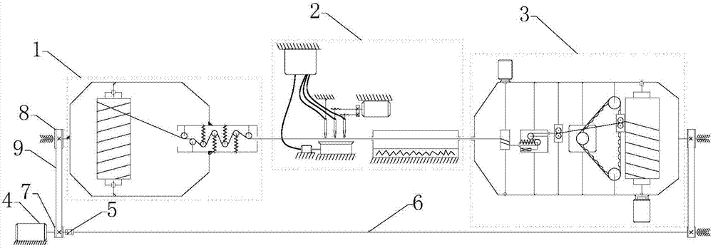
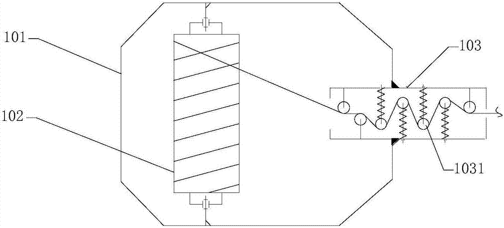
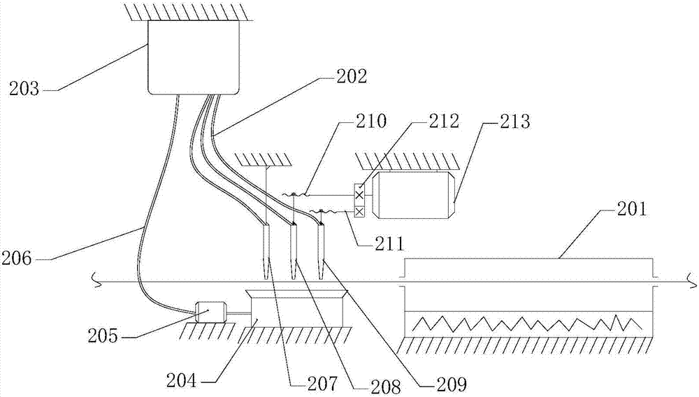
[0028] like Figures 1 to 4 As shown, the present invention provides a helical single-yarn piezoelectric jet dyeing device, which includes a rotary pay-off module 1, a piezoelectric jet-dyeing module 2 and a rotary wire take-up module 3, which are arranged in sequence, and the rotary pay-off module 1 It rotates synchronously in the same direction as the rotary take-up module 3, and the yarn between them rotates around the central axis of the yarn in the piezoelectric jet dyeing module 2, and the rotating yarn is in the piezoelectric jet dyeing module. 2 accepts the jet dyeing of a plurality of piezoelectric nozzles, the rotary pay-off module 1 is used to supply the yarn to be dyed to the piezoelectric jet dye mo...


PUM


Abstract

The invention relates to the technical field of yarn dyeing, in particular to a spiral single-yarn piezoelectric spray dyeing device. The device comprises a rotary yarn pay-off module, a piezoelectric spray dyeing module and a rotary yarn take-up module which are connected in sequence. The rotary yarn pay-off module and the rotary yarn take-up module synchronously rotate in the same direction, yarn between the rotary yarn pay-off module and the rotary yarn take-up module rotates around the center axis of yarn in the piezoelectric spray dyeing module, the rotating yarn is subjected to spray dyeing of a plurality of piezoelectric spray heads in the piezoelectric spray dyeing module, the rotary yarn pay-off module is used for supplying yarn to be spray-dyed to the piezoelectric spray dyeing module, and the rotary yarn take-up module is used for the yarn which is spray-dyed by the piezoelectric spray dyeing module and dried is spooled into rolls. The device has the advantages that the rotationally advancing yarn is coated through the piezoelectric spray heads arranged above the yarn, the yarn can be evenly spray-dyed after the spray dyeing tracks of the spray heads are overlapped, the device is more even than single-side spray dyeing of traditional spray dyeing, more dyeing liquid is saved compared with traditional dip dyeing, and different sections of one piece of yarn can be dyed with different colors.

Description

technical field [0001] The invention relates to the technical field of yarn dyeing, in particular to a helical single-yarn piezoelectric jet dyeing device. Background technique [0002] Most of the existing single yarn dyeing devices adopt two methods of dip dyeing and jet dyeing. Equipment using the dip dyeing method, including patents ZL201310550132.7, ZL201220183093.2 and ZL 201310551500.X, will face problems such as insufficient use of dye liquor and waste, and a yarn can only be dyed in one color. Existing equipment using jet dyeing, including ZL201420667869.7 and ZL200410028019.3, all use one-side jetting, which is likely to cause uneven dyeing of yarns. At the same time, the nozzles of the existing jet dyeing equipment are prone to fugitive dust during high-speed operation, and because the control of the jet dye dosage is not precise enough, it is easy to cause dye particles to float in the air, thereby polluting the air and affecting the quality of the yarn. SUMMA...

Claims


Application Information

Patent Timeline
Patent Type & Authority Applications(China)
IPC IPC(8): D06B1/02D06B23/20D06B23/04
CPCD06B1/02D06B23/04D06B23/20D06B11/0023
Inventor 徐杰柯文博易长海邹汉涛刘雪亭黄平
Owner WUHAN TEXTILE UNIV
Why Eureka
Try Eureka