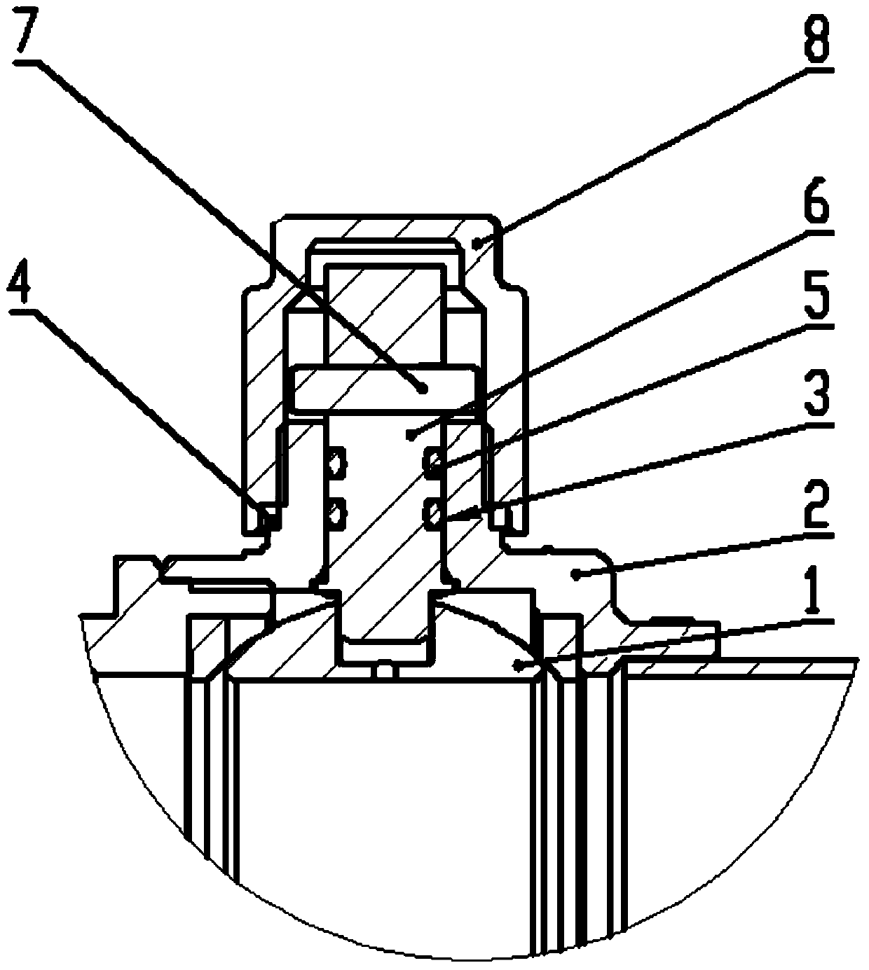
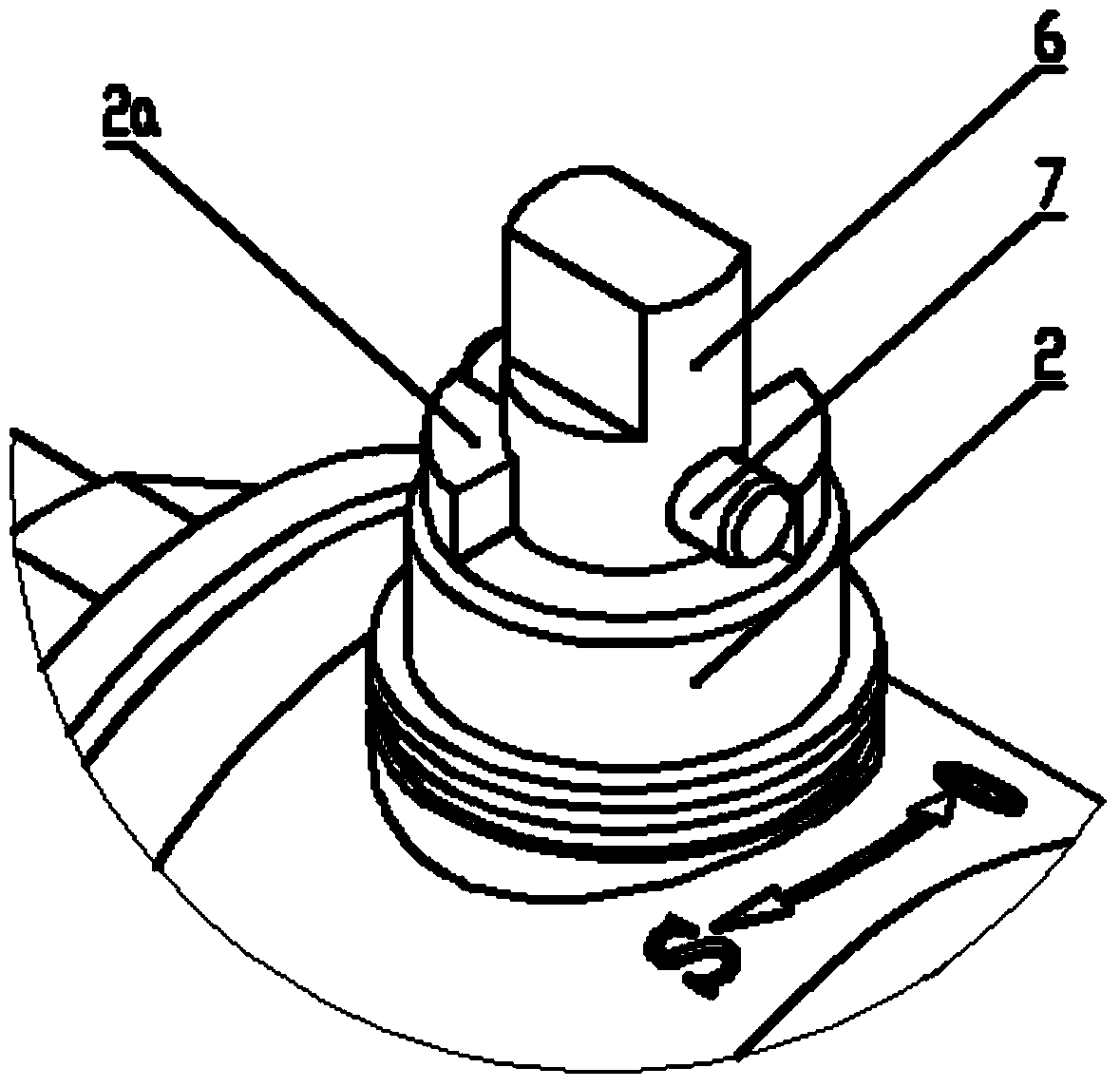
Ball valves and stop devices for ball valve stems
A technology for stoppers and valve stems, which is applied to valve devices, devices to prevent accidental or unauthorized actions, cocks including cut-off devices, etc. Easy to lose and other issues
- Summary
- Abstract
- Description
- Claims
- Application Information
AI Technical Summary
Problems solved by technology
Method used
Image
Examples
Embodiment 1
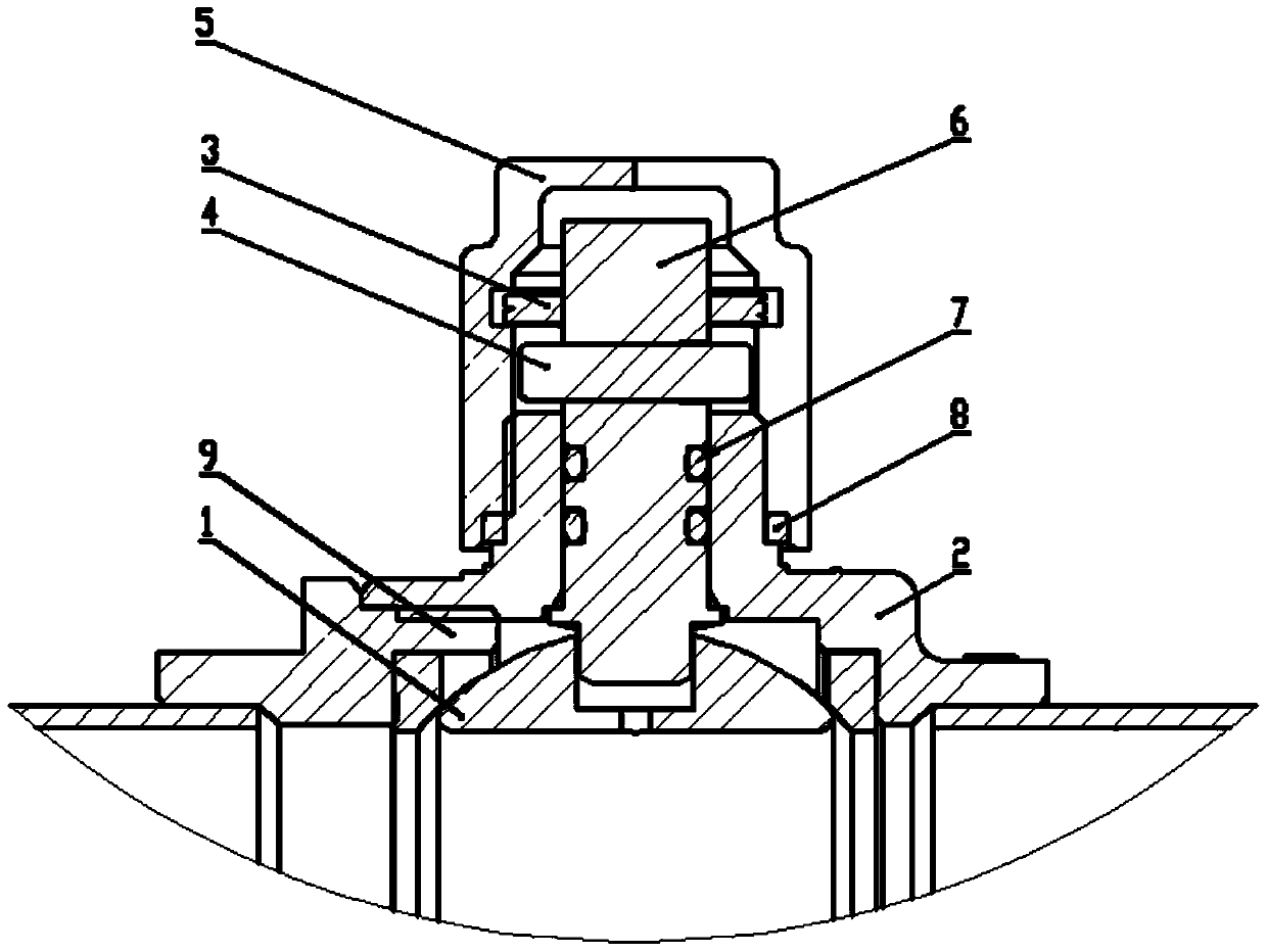
[0053] like Figure 8-10 as shown, Figure 8 for Figure 5 Structural schematic diagram of the middle stop ring 3; Figure 9 for Figure 5 Axial sectional view of middle valve cap 5; Figure 10 for Figure 9 The three-dimensional schematic diagram of the middle valve cap 5.
[0054] In this embodiment, the inner wall of the bonnet 5 is provided with an internal thread 52, and the outer circumference of the stop ring 3 is correspondingly provided with a matching external thread 312. Since the stop ring 3 is set as an oblong shape in this solution, the outer Threads 312 can be formed on the circular arcs at both ends of the stop ring 3. The middle part of the stop ring 3 has a first insertion hole 311 for the valve stem 6 to be inserted into. Bit pin 32. The first insertion hole 311 is also oblong (also can be square or rectangular), which is the same shape as the upper end of the valve stem 6. When the valve stem 6 is inserted into the first insertion hole 311, the valve...
Embodiment 2
[0060] like Figure 11-12 as shown, Figure 11 It is a structural schematic diagram of the stop device in the second embodiment of the ball valve provided by the present invention; Figure 12 for Figure 11 Schematic diagram of the structure of the middle limiting piece 3'.
[0061] The structure of the ball valve in this embodiment is basically the same as that in Embodiment 1, the difference lies in the manner in which the stop ring 3 is limited to the bonnet 5 . This stop device also includes a limit piece 3' fixed with the stop ring 3, such as Figure 12 As shown, the limiting piece 3' is provided with a second socket 3'2 for the valve stem 6 to be inserted, and the outer periphery of the limiting piece 3' is provided with a limiting card edge 3'1, and the limiting card edge 3' in this embodiment 1. It is formed by a plurality of strip-shaped limit whiskers 3'1a arranged side by side, that is, the limit card edge 3'1 is in the shape of a comb as shown in the figure, an...
Embodiment 3
[0068] In this embodiment, the limiting card edge 3'1 can be directly arranged on the outer periphery of the stop ring 3, without separately setting the limiting piece 3'. The structure of the limiting card edge 3'1 can be the same as that of embodiment 2, that is, it is arranged in a comb-like shape, or a material that can shrink and rebound is selected. The limiting card edge 3'1 is also preferably inclined to prevent the limit The card edge 3'1 breaks away from the limiting groove 51.
[0069] In addition to the above embodiments, other ways can also be used to realize the circumferentially rotatable limitation of the stop ring 3 in the valve cap 5 . The inner wall of the bonnet 5 may not be provided with a limit groove 51, and the stop ring 3 can be directly placed in the bonnet 5, and then an anti-off piece is screwed into the bonnet 5 to prevent the stop ring 3 from breaking away from the valve cap. Cap 5; or, the bonnet 5 is designed as a split structure, and the bonne...
PUM
 Abstract
Description
Claims
Application Information
 - R&D
- Intellectual Property
- Life Sciences
- Materials
- Tech Scout
- Unparalleled Data Quality
- Higher Quality Content
- 60% Fewer Hallucinations
Browse by: Latest US Patents, China's latest patents, Technical Efficacy Thesaurus, Application Domain, Technology Topic, Popular Technical Reports.
© 2025 PatSnap. All rights reserved.Legal|Privacy policy|Modern Slavery Act Transparency Statement|Sitemap|About US| Contact US: help@patsnap.com


