Convenient-to-use drying equipment for textiles and chemical fibers

The technology of drying equipment and chemical fiber is applied in the field of textile and chemical fiber processing, which can solve the problems of inconvenient use and poor drying effect, and achieve the effects of good drying effect, avoiding wrinkles and saving labor.

Inactive Publication Date: 2017-06-30
肖叶
0 Cites 2 Cited by

AI-Extracted Technical Summary

Problems solved by technology

[0005] Aiming at the deficiencies of the prior art, the present invention provides an easy-to-use drying equ...

Method used

In sum, this easy-to-use textile and chemical fiber drying equipment, by being provided with the first rotating shaft 14, the second rotating shaft 9 and the rotating rod 8, in the main bearing 13, the first bearing 10, the second Under the action of the bearing 17 and the sealed bearing 7, using the rotational force of the motor 23, the textiles on the first coil 21 can be rotated and dried in a triangular manner, ensuring sufficient contact between the textiles and the heat, while avoiding accumulation and drying The disadvantages of the textiles are that by setting the third rotating shaft 5, the textiles can be effectively contacted, and the heat of the third rotating shaft 5 can be used to effectively dry the textiles, and the drying effect is good. The dynamic bearing 6 and the second driven bearing 18 ensure the flexible rotation of the third rotating shaft 5, and can effectively unfold the textiles, avoiding the wrinkles of the textiles. By providing the first threaded ring 20 and the second threaded ring 25 , can effectively limit the first wire coil 21 and the second wire coil 24, effectively saves manpower, and is more convenient to use.
Please refer to Fig. 1-2, the present invention provides a kind of technical scheme: a kind of drying equipment for textile chemical fiber that is easy to use, comprises drying equipment body 1, and the top of drying equipment body 1 is provided with cooling holes 11 respectively and the notch 16, and the heat dissipation hole 11 is located on the left side of the notch 16, the inside of the notch 16 is placed with a sealing plug 12 suitable for the notch 16, and the top of the sealing plug 12 is fixedly connected with a han...

Abstract

The invention discloses an easy-to-use drying equipment for textile and chemical fiber, which comprises a drying equipment body, an electric heating plate is fixedly connected to the inner bottom wall of the drying equipment body, and an electric heating plate is fixedly connected to the inside of the drying equipment body. The baffle plate that is suitable for the drying equipment body, and the baffle plate is located on the upper part of the electric heating plate, and the middle part of the baffle plate is provided with equidistantly arranged through holes, and the inner wall of the drying equipment body is fixedly connected with the first bearing, sealing bearings and equidistant first driven bearings. The easy-to-use drying equipment for textile and chemical fibers can perform triangular rotation drying on the textiles on the first coil, ensuring sufficient contact between the textiles and the heat, while avoiding the disadvantages of accumulation drying, and being able to dry the textiles. Effective drying treatment, good drying effect, can effectively unfold the textiles, avoid the wrinkles of the textiles, effectively save manpower, and be more convenient to use.

Application Domain

Technology Topic

Image

  • Convenient-to-use drying equipment for textiles and chemical fibers
  • Convenient-to-use drying equipment for textiles and chemical fibers

Examples

  • Experimental program(1)

Example Embodiment

[0024] The technical solutions in the embodiments of the present invention will be clearly and completely described below in conjunction with the accompanying drawings in the embodiments of the present invention. Obviously, the described embodiments are only a part of the embodiments of the present invention, rather than all the embodiments. Based on the embodiments of the present invention, all other embodiments obtained by those of ordinary skill in the art without creative work shall fall within the protection scope of the present invention.
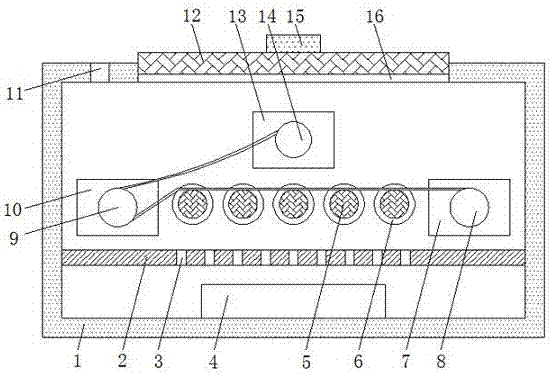
[0025] See Figure 1-2 , The present invention provides a technical solution: an easy-to-use drying equipment for textile and chemical fiber, including a drying equipment body 1, the top of the drying equipment body 1 is provided with a heat dissipation hole 11 and a gap 16, and the heat dissipation hole 11 is located On the left side of the notch 16, a sealing plug 12 adapted to the notch 16 is placed inside the notch 16, and a handle 15 is fixedly connected to the top of the sealing plug 12, which can effectively pick and place the sealing plug 12, thereby enabling the textile and chemical fiber The electric heating plate 4 is fixedly connected to the inner bottom wall of the drying equipment body 1. The electric heating plate 4 is an electric heating device that winds the resistance heating wire on the mica board. To convert electrical energy into thermal energy and release heat, the electric heating plate 4 is an electric heating device known in the prior art. For those skilled in the art, the principle and structure are clear and complete. Therefore, no further Too much description, the inside of the drying equipment body 1 is fixedly connected with a baffle 2 that matches the drying equipment body 1, and the baffle 2 is located on the upper part of the electric heating plate 4, and the middle of the baffle 2 is arranged equidistantly. The through hole 3 ensures effective heat dissipation.
[0026] A first bearing 10, a sealed bearing 7 and a first driven bearing 6 arranged equidistantly are fixedly connected to the inner side wall of the drying equipment body 1, and the first driven bearing 6 is located between the first bearing 10 and the sealed bearing 7 , The main bearing 13 is fixedly connected to the inner side wall of the drying equipment body 1, and the main bearing 13 is located above the first driven bearing 6, the first bearing 10 and the sealed bearing 7 are both located at the same level, and the main bearing 13 is located at the A bearing 10 is located at the upper right and the main bearing 13 is located at the upper left of the sealed bearing 7.
[0027] The inner ring of the main bearing 13 is fixedly connected with a first rotating shaft 14, a first coil 21 is sleeved on the first rotating shaft 14, and an end of the first rotating shaft 14 away from the main bearing 13 is threadedly connected with a first threaded ring 20, The inner ring of the first bearing 10 is fixedly connected with the second rotating shaft 9, and the inner ring of each first driven bearing 6 is fixedly connected with the third rotating shaft 5, and the third rotating shaft 5 can effectively absorb heat. Thus, the heat can be transferred to the textile, and the textile can be dried quickly.
[0028] The outer side of the drying equipment body 1 is fixedly connected with a supporting table 22, the top of the supporting table 22 is fixedly connected with a motor 23, the output end of the motor 23 is fixedly connected with a rotating rod 8, and the end of the rotating rod 8 away from the motor 23 passes through the drying in turn The device body 1 and the sealed bearing 7 extend to the inside of the drying device body 1. The outer surface of the rotating rod 8 and the inner ring of the sealed bearing 7 are fixedly connected, and the second coil 24 is sleeved on the rotating rod 8, and the rotating rod 8 is far away A second threaded ring 25 is threadedly connected to one end of the sealed bearing 7.
[0029] A fixing plate 19 is fixedly connected to the inner side wall of the drying equipment body 1, and a side surface of the fixing plate 19 close to the main bearing 13 is fixedly connected to a second bearing 17 and a second driven bearing 18 arranged equidistantly, and the second follower The moving bearing 18 corresponds to the first driven bearing 6 one by one, the number of the first driven bearing 6 and the second driven bearing 18 is at least five, and the five first driven bearings 6 and the five second driven bearings The moving bearings 18 are all located on the same level. The center point of the first bearing 10, the center point of the sealed bearing 7 and the center points of the five first driven bearings 6 are all located at the same level. The center points of the second bearing 17 and five The center points of the two second driven bearings 18 are all at the same level, and the center point of the first bearing 10 and the center point of the second bearing 17 are at the same level. The third rotating shaft 5 is far away from the first driven bearing 6 One end is fixedly connected to the inner ring of the second driven bearing 18. The second bearing 17 is located on the left side of the second driven bearing 18, and the end of the second rotating shaft 9 away from the first bearing 10 is fixed to the inner ring of the second bearing 17 The connection is achieved by providing the first rotating shaft 14, the second rotating shaft 9 and the rotating rod 8, under the action of the main bearing 13, the first bearing 10, the second bearing 17 and the sealed bearing 7, the rotating force of the motor 23 is utilized, The textiles on the first thread reel 21 can be dried by triangular rotation. The first threaded ring 20 and the second threaded ring 25 can respectively fasten or loosen the first thread reel 21 and the second thread reel 24, Similar to the function of a nut, the first wire reel 21 and the second wire reel 24 can be separately limited, avoiding the slipping phenomenon of the first wire reel 21 and the second wire reel 24, and the drying equipment is more convenient to use and save It saves time and effort, and the drying effect is good.
[0030] Working principle: Remove the sealing plug 12, set the first thread roll 21 with wet textile and chemical fiber products on the first rotating shaft 14, and use the first threaded ring 20 to limit the position, and set the second thread roll 24 on the On the rotating rod 8, and the second thread 25 ring is used to limit the position, one end of the textile chemical fiber product is passed around the second rotating shaft 9 and fixed on the second thread roll 24. At this time, the textile chemical fiber product is triangular, and the textile chemical fiber The product is in contact with the third rotating shaft 5, and the electric heating plate 4 and the motor 23 are respectively connected to the municipal power supply. The heat generated by the electric heating plate 4 will be dissipated through the through hole 3, and the textiles will be dried. 23 drives the rotating rod 8 to rotate and wind the textile. Under the action of the main bearing 13, the first bearing 10, the second bearing 17, the first driven bearing 6 and the second driven bearing 18, the first The rotating shaft 14, the second rotating shaft 9 and the third rotating shaft 5 will rotate and transport the textiles, so that the textiles can be evenly dried, which saves manpower, is convenient to use, and has a good drying effect.
[0031] In summary, this easy-to-use drying equipment for textile and chemical fiber is provided with the first rotating shaft 14, the second rotating shaft 9 and the rotating rod 8, and the main bearing 13, the first bearing 10, the second bearing 17 and Under the action of the sealed bearing 7, the rotation force of the motor 23 can be used to dry the textiles on the first thread roll 21 in a triangular manner, which ensures sufficient contact between the textiles and heat, and avoids the disadvantages of accumulation and drying. By providing the third rotating shaft 5, the textiles can be effectively contacted, and the heat of the third rotating shaft 5 can be used to effectively dry the textiles, and the drying effect is good. The first driven bearing 6 is provided. And the second driven bearing 18 to ensure the flexible rotation of the third rotating shaft 5, which can effectively unfold the textiles, and avoid the wrinkles of the textiles. By providing the first threaded ring 20 and the second threaded ring 25, the The first thread reel 21 and the second thread reel 24 are effectively limited, which effectively saves manpower and is more convenient to use.
[0032] It should be noted that in this article, relational terms such as first and second are only used to distinguish one entity or operation from another entity or operation, and do not necessarily require or imply one of these entities or operations. There is any such actual relationship or order between. Moreover, the terms "include", "include" or any other variants thereof are intended to cover non-exclusive inclusion, so that a process, method, article or device including a series of elements not only includes those elements, but also includes those that are not explicitly listed Other elements of, or also include elements inherent to this process, method, article or equipment. Without more restrictions. The sentence "including an element defined by ... does not exclude the existence of other identical elements in the process, method, article, or equipment including the element."
[0033] Although the embodiments of the present invention have been shown and described, those of ordinary skill in the art can understand that various changes, modifications, and substitutions can be made to these embodiments without departing from the principle and spirit of the present invention. And variations, the scope of the present invention is defined by the appended claims and their equivalents.

PUM

no PUM

Description & Claims & Application Information

We can also present the details of the Description, Claims and Application information to help users get a comprehensive understanding of the technical details of the patent, such as background art, summary of invention, brief description of drawings, description of embodiments, and other original content. On the other hand, users can also determine the specific scope of protection of the technology through the list of claims; as well as understand the changes in the life cycle of the technology with the presentation of the patent timeline. Login to view more.

Similar technology patents

Classification and recommendation of technical efficacy words

  • Good drying effect
  • Avoid wrinkles

Pipe cavity bracket

ActiveCN105496603AAvoid wrinklesAvoid blood blockageStentsBlood vesselsBlood streamCavity wall
Owner:LIFETECH SCIENTIFIC (SHENZHEN) CO LTD

Cloth ironing device

Owner:桐梓县创兴自动化设备有限公司

Display device

Owner:WUHAN CHINA STAR OPTOELECTRONICS SEMICON DISPLAY TECH CO LTD
Why Eureka
Try Eureka