Panoramic optical lens and image acquisition device

An optical lens and image acquisition technology, applied in the field of imaging, can solve the problems of low light quantity of the photosensitive module, difficult to obtain a clear image, difficult to control the installation accuracy, etc., to achieve the effect of compact device design, easy optical design, and improved imaging quality.

Inactive Publication Date: 2017-06-30
BOLY MEDIA COMM SHENZHEN
View PDF6 Cites 5 Cited by
  • Summary
  • Abstract
  • Description
  • Claims
  • Application Information

AI Technical Summary

Problems solved by technology

This technology has less distortion, but it needs to set discrete reflective elements, the installation accuracy is not easy to control, and the amount of light actually entering the photosensitive module is small, making it difficult to obtain a clear image

Method used


Image

  • Panoramic optical lens and image acquisition device
  • Panoramic optical lens and image acquisition device
  • Panoramic optical lens and image acquisition device

Examples


Embodiment 1

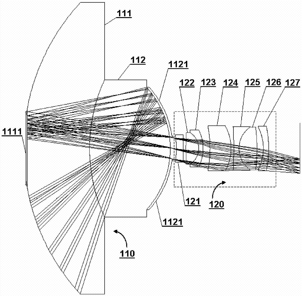
[0020] An embodiment of the panoramic optical lens according to the present invention can refer to figure 1 , including a catadioptric lens group 110 and a first lens lens group 120 .

[0021] In this article, "front surface" and "rear surface" are used to describe two opposite surfaces along the optical axis on an optical lens, where the surface through which incident light passes first is called the front surface, and the surface that passes through it later is called the rear surface . In a catadioptric lens set, the incident light may pass through certain surfaces multiple times due to reflections, and the "front surface" and "rear surface" are defined in the order in which the incident light passes for the first time.

[0022] The catadioptric lens group 110 includes two catadioptric mirrors cemented together, that is, a first catadioptric mirror 111 and a second catadioptric mirror 112 , and this kind of cemented mirror is not only simple in processing but also superior...

Embodiment 2

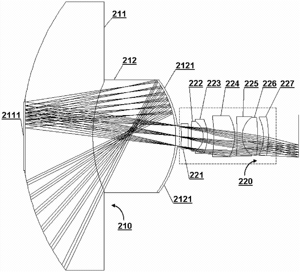
[0037] Another embodiment of the panoramic optical lens according to the present invention can refer to figure 2 , including a catadioptric lens group 210 and a first lens lens group 220 .

[0038] This embodiment is similar to Embodiment 1. The catadioptric lens group 210 includes two catadioptric mirrors glued together, that is, the first catadioptric mirror 211 and the second catadioptric mirror 212. The center of the front surface of the first catadioptric mirror is The area is the reflection area 2111, the central area of ​​the rear surface of the second catadioptric mirror is the transmission area, and the remaining areas are the reflection area 2121; the first lens group is composed of seven lenses, and the order along the optical path is the first lens with negative diopter. One lens 221, the second lens 222 with positive diopter, the third lens 223 with negative diopter, the fourth lens 224 with negative diopter, the fifth lens 225 with negative diopter, and the sixt...

Embodiment 3

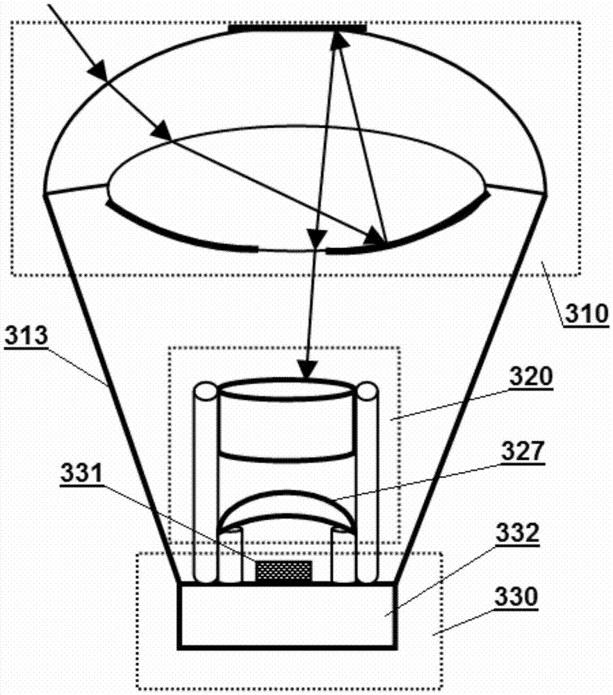
[0041] An embodiment of the panoramic image acquisition device according to the present invention may refer to image 3 , including a panoramic optical lens and a first image acquisition module 330 .

[0042] The panoramic optical lens can specifically adopt various implementation methods according to the present invention, for example, adopt the structure described in Embodiment 1 or 2, including the catadioptric lens group 310 and the first lens lens group 320 , and the internal structure will not be repeated.

[0043] In this embodiment, the first lens group 320 is an auto-focus lens group, that is, at least one lens 327 can move along the optical axis, image 3 The position of the lens 327 shown in is only schematic, and may actually be any lens in the first lens group. Specifically, the auto-focus can be driven by a traditional voice coil motor or a stepping motor, or by a polyhedral ultrasonic motor, a disk electromagnetic motor, etc. proposed by one of the inventors of...


PUM


Abstract

The invention relates to a panoramic optical lens and an image acquisition device. The panoramic optical lens comprises a catadioptric lens group (110) and a lens group (120). The catadioptric lens group comprises two catadioptric lenses which are glued together; the central area of the front surface of the first catadioptric lens is a reflection area, and other areas are transmission areas; the central area of the rear surface of the second catadioptric lens is a transmission area, and other areas are reflection areas; and the lens group is arranged on the optical path behind the catadioptric lens group. The catadioptric lens group combining refraction and reflection is employed to collect incident light, light is refracted, then reflected, then refracted and then reflected between the two catadioptric lenses and is converged for many times, the resolution of the edge of the field of view can be effectively increased, the imaging quality is improved, and the image acquisition device is designed more compactly.

Description

technical field [0001] The invention relates to the field of image technology, in particular to a panoramic optical lens and a corresponding panoramic image acquisition device. Background technique [0002] Generally, a device capable of collecting images of a 360-degree circular area is called a panoramic image collection device. With the development of digital imaging technology, especially the continuous improvement of the number of pixels and image processing capabilities, the use of panoramic image acquisition devices is becoming more and more common. [0003] The existing panoramic imaging technologies include the following: [0004] 1. Use an ordinary image acquisition device to rotate around the axis to shoot, and then stitch the images seamlessly to obtain a panoramic image. This method requires a large number of image stitching calculations, which is difficult to guarantee real-time performance, and cannot continuously shoot the same location, making it difficult...

Claims


Application Information

Patent Timeline
Patent Type & Authority Applications(China)
IPC IPC(8): G02B13/06G02B13/00G03B37/00
CPCG02B13/006G02B13/06G03B37/00G02B17/08
Inventor 胡笑平蒋国銮
Owner BOLY MEDIA COMM SHENZHEN
Why Eureka
Try Eureka