
Bandgap reference voltage source with high order temperature compensation

A technology of high-order temperature compensation and reference voltage source, applied in the direction of adjusting electrical variables, control/regulation systems, instruments, etc., can solve the problems of high circuit complexity, large layout area, high supply voltage, etc., achieve low temperature coefficient, reduce Circuit complexity, effect of higher order temperature compensation

Active Publication Date: 2017-06-30
SOUTH CHINA UNIV OF TECH
View PDF7 Cites 1 Cited by
  • Summary
  • Abstract
  • Description
  • Claims
  • Application Information

AI Technical Summary

Problems solved by technology

[0004] Although the traditional bandgap reference voltage source can better eliminate the temperature-related primary term through linear combination, its temperature characteristics are still not ideal due to the high-order term in the expression of the base-emitter voltage of the bipolar transistor. Especially for low-voltage output reference sources, the temperature coefficient can reach hundreds of ppm; in addition, because the traditional bandgap reference voltage source structure needs to use operational amplifiers and more resistors, the circuit complexity is high, the supply voltage is high and the layout area is relatively high. larger

Method used


Image

  • Bandgap reference voltage source with high order temperature compensation
  • Bandgap reference voltage source with high order temperature compensation
  • Bandgap reference voltage source with high order temperature compensation

Examples


Embodiment

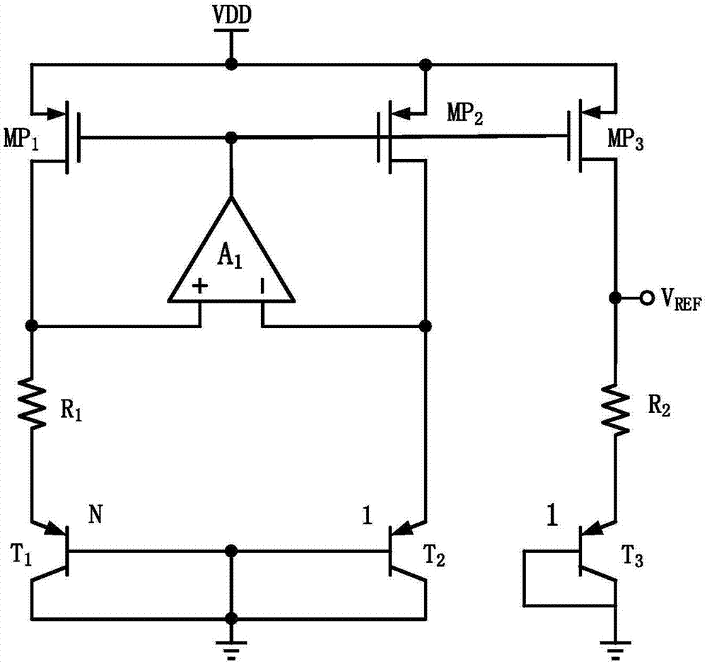
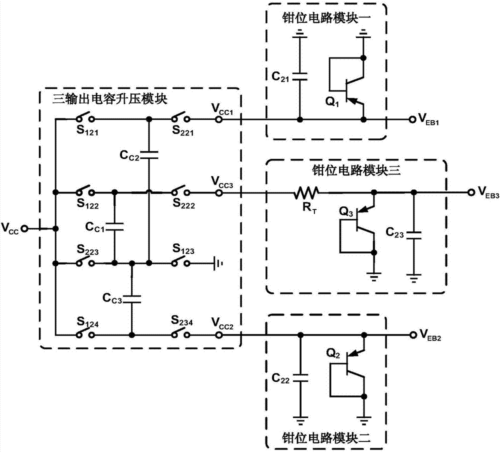
[0029] The structure of the traditional bandgap reference voltage source is as follows figure 1 As shown, this embodiment provides a bandgap reference voltage source with high-order temperature compensation based on the improvement of the traditional bandgap reference voltage source, such as figure 2 As shown, it includes a three-output switched capacitor converter, switched capacitor module 1 and switched capacitor module 2, where the input voltage V CC connected to the input terminals of the three-output switched capacitor converter, and the output terminals of the three-output switched capacitor converter respectively output three bias voltages V EB1 , V EB2 and V EB3 , the first bias voltage V EB1 Connected to the first input terminal of the switched capacitor module one, the second bias voltage V EB2 Connected to the second input terminal of the switched capacitor module one and the second input terminal of the switched capacitor module two, the third bias voltage V ...


PUM


Abstract

The invention discloses a bandgap reference voltage source with high order temperature compensation. The bandgap reference voltage source with the high order temperature compensation comprises a three-output switching capacitor converter, a first switched capacitor module and a second switched capacitor module, wherein an input voltage VCC is connected to the input terminal of the three-output switching capacitor converter, and the output terminal of the three-output switching capacitor converter respectively outputs three paths of bias voltages VEB1, VEB2 and VEB3; the first path of bias voltage VEB1 is connected to the first input terminal of the first switched capacitor module, and the second path of bias voltage VEB2 is connected to the second input terminal of the first switched capacitor module and the second input terminal of the second switched capacitor module; the third path of bias voltage VEB3 is connected to the third input terminal of the second switched capacitor module, and the output terminal of the first switched capacitor module is connected to the first inlet terminal of the second switched capacitor module; the output terminal of the second switched capacitor module outputs a reference voltage VREF. The bandgap reference voltage source with the high order temperature compensation provided by the invention is based on a switched capacitor structure, thus greatly reducing the complexity of a circuit, realizing the elimination of a high order term and the bandgap reference high temperature compensation, and obtaining a lower temperature coefficient.

Description

technical field [0001] The invention relates to the design fields of analog integrated circuits and bandgap references, in particular to a bandgap reference voltage source with high-order temperature compensation. Background technique [0002] Bandgap reference voltage source is a basic unit module in integrated circuits, widely used in various analog integrated circuit chips, such as LNA, Mixer, ADC, high-precision comparator, voltage regulator, DC / DC converter, etc., as well as digital Mixed-mode integrated circuit chips, such as D-LDO, VCO, PLL, etc. [0003] The traditional bandgap reference voltage source includes bipolar transistors T1, T2, T3, error amplifier A1, integrated MOS transistors MP1, MP2, MP3 and resistors R1, R2, which are obtained by mirroring the branch current of MP1 and making it flow through resistor R2 The temperature-related voltage term is connected in series with T3, and finally an output voltage VREF that is basically temperature-independent is ...

Claims


Application Information

Patent Timeline
Patent Type & Authority Applications(China)
IPC IPC(8): G05F1/567
CPCG05F1/567
Inventor 李斌陈兆权黄沫刘洋吴朝晖严耀锋
Owner SOUTH CHINA UNIV OF TECH
Learn More