
Adjustment of dipyramidal-surface enveloping worm emery cutters

A technology of toroidal worm and adjustment method, which is applied in the direction of worms, components with teeth, belts/chains/gears, etc., and can solve problems such as the inability to realize the tooth surface processing of toroidal worms

Active Publication Date: 2017-06-30
河北涞博传动机械制造有限公司
View PDF13 Cites 7 Cited by
  • Summary
  • Abstract
  • Description
  • Claims
  • Application Information

AI Technical Summary

Problems solved by technology

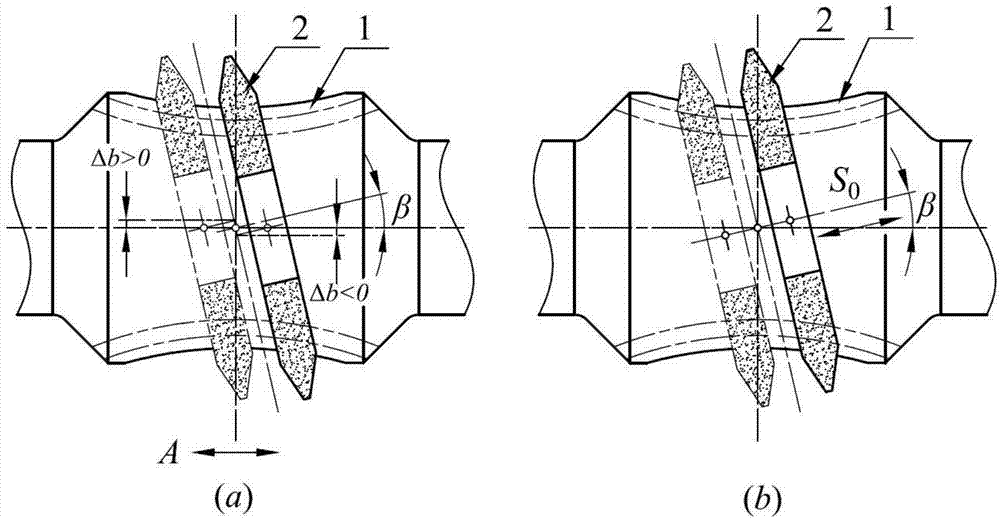
The disadvantage of this patent is that when the transverse feed carriage is fed along the A axis to process the tooth surface of the toroidal worm, a Δb modification perpendicular to the axial direction of the toroidal worm will be produced at the same time. Therefore, the processed product has an inclination angle The tooth surface of the toroidal worm with comprehensive modification of β and Δb cannot realize the processing of the tooth surface of the toroidal worm with only β angle modification

Method used


Image

  • Adjustment of dipyramidal-surface enveloping worm emery cutters
  • Adjustment of dipyramidal-surface enveloping worm emery cutters
  • Adjustment of dipyramidal-surface enveloping worm emery cutters

Examples


Embodiment 1

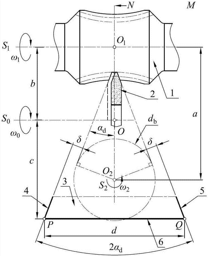
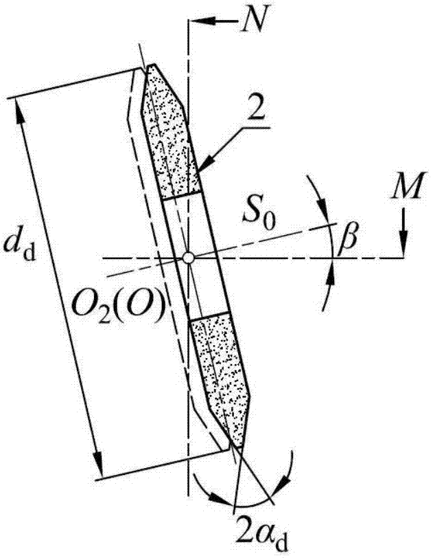
[0023] Embodiment 1: the center distance of the toroidal worm pair a=240mm, the transmission ratio i 12 =40, the number of heads of the toroidal worm (1) Z 1 =1, the direction of rotation is right-handed, the diameter of the root circle of the throat is d f1 =61mm, the normal alveolar width e of the partial annulus of throat n1 =17.58mm, the number of worm gear teeth meshing with it Z 2 =40, end modulus m t =10mm, diameter of main base circle d b =153.20mm, the diameter of the indexing circle is d 2 =400mm, tooth profile angle α of double cone grinding wheel (2) d =20°, diameter d d =160mm;

[0024] Set the rotation axis of the toroidal worm (1) as S 1, the rotation axis of the double-cone grinding wheel (2) is S 0 , by two parallel axes S 0 and S 1 Determine the base surface M, the main base circle of the worm gear meshed with the toroidal worm (1) is located in the base surface M, and the center of the circle is O 2 , over O 2 point and perpendicular to the base...

Embodiment 2

[0035] Embodiment 2: Increase the center distance a=400mm and transmission ratio i of the toroidal worm pair 12 =40, the number of heads of the toroidal worm (1) Z 1 =1, the direction of rotation is right-handed, the diameter of the root circle of the throat is d f1 =110.3mm, the number of worm gear teeth meshing with it Z 2 =40, end modulus m t =16.5mm, the diameter of the indexing circle is d 2 =660mm, tooth profile angle α of double cone grinding wheel (2) d =20°, diameter d d = 350mm, select the inclination angle β of the double-cone grinding wheel (2) = 10°, and calculate the normal slot width e n1 =28.59mm, diameter of main base circle of worm gear d b =259.50mm, parameter 2α of reference table (3) d , c and d remain unchanged, calculate the grinding wheel distance b = 169.85mm, offset distance δ = 1.889mm, according to the same adjustment method as above, by adjusting the grinding wheel distance b, offset distance δ and inclination β, determine the double cone gr...


PUM

PropertyMeasurementUnit
Center distanceaaaaaaaaaa
Diameteraaaaaaaaaa

Abstract

The invention relates to the technical field of double enveloping worm gear pair manufacturing, and discloses an adjustment method of enveloping worm emery cutters with dipyramidal surface. During the processing of enveloping worm tooth surface, by the means of adjusting the emery cutter distance between dipyramidal-surface emery cutters and enveloping worms as well as the offset between the generatrices at the both sides of dipyramidal-surface emery cutters and the both sides of a datum plane, the relative position of the dipyramidal-surface emery cutters and the enveloping worms is determined and the dipyramidal-surface emery cutters relatively move according to the preset transmission ratio with the enveloping worms, thereby obtaining dipyramidal-surface enveloping worm tooth surface. By the adoption of dipyramidal-surface emery cutters in the same tooth profile angles and different diameters, the processing of enveloping worm tooth faces in different parameters can be realized.

Description

technical field [0001] The invention belongs to the technical field of secondary enveloping toroidal worm pair manufacturing, in particular to a method for adjusting a double-cone enveloping toroidal worm grinding wheel. Background technique [0002] In the field of toroidal worm transmission, the most widely used are the planar double-enveloping toroidal worm pair and the double-cone double-enveloping toroidal worm pair. Among them, the double-cone double-enveloping toroidal worm pair The tooth surface of the worm is processed separately by the cone surfaces on both sides of the double-cone grinding wheel. Since the cone surfaces on both sides of the double-cone grinding wheel are the processing surfaces, when processing the tooth surfaces of different sides of the toroidal worm, the toroidal worm or the double-cone grinding wheel does not need to turn around. The auxiliary time is reduced. At the same time, in the case of multi-head and small transmission ratio, the toroid...

Claims


Application Information

Patent Timeline
IPC IPC(8): G06F17/50B23F13/00
CPCB23F13/00B23F13/006G06F30/17
Inventor 王文昌张丽红李海涛董学朱张德华
Owner 河北涞博传动机械制造有限公司
Learn More