Metal rubber metal wire fretting wear and fatigue test device and test method thereof
A technology of fretting wear and metal rubber, which is applied in the direction of testing wear resistance, etc., can solve the problem of the inability to achieve accurate and controllable wire test angles, the inability to ensure accurate and controllable wire contact positions, and the inability to combine fretting wear and fatigue Test functions and other issues to achieve the effect of avoiding motion interference, easy to use, and strong practicability
- Summary
- Abstract
- Description
- Claims
- Application Information
AI Technical Summary
Problems solved by technology
Method used
Image
Examples
Embodiment 1
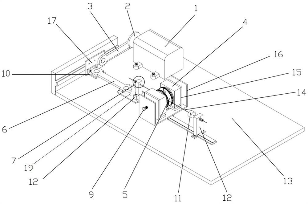
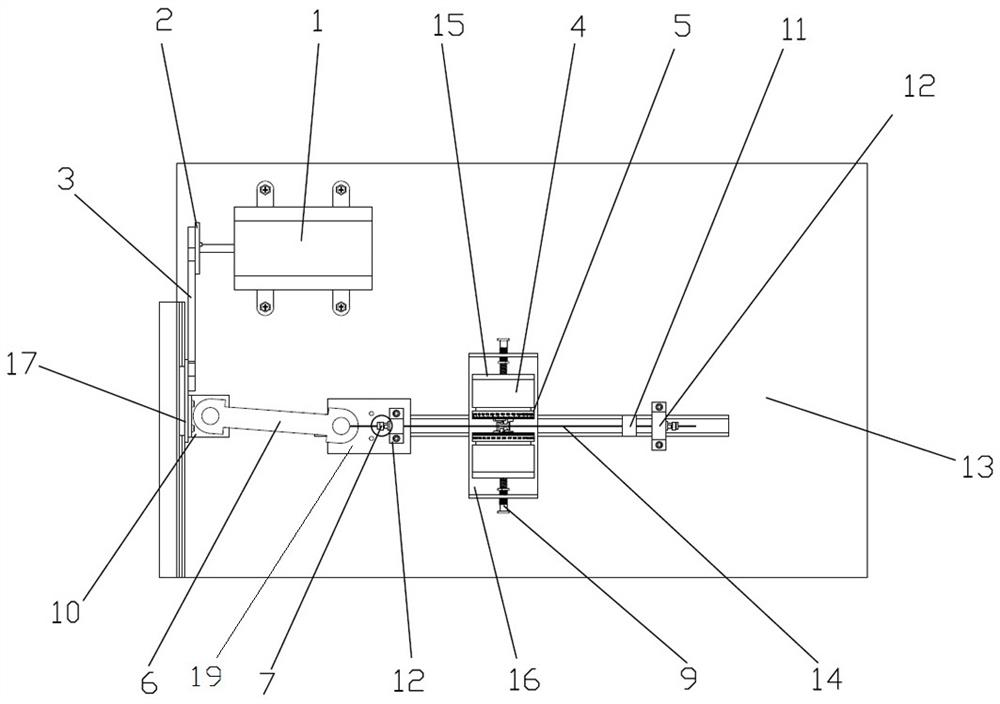
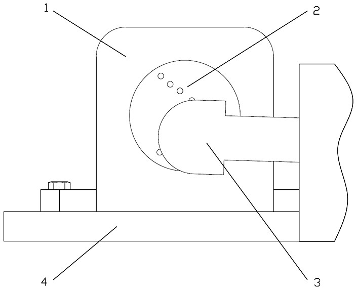
[0039] Example 1: as Figures 1~9As shown in the figure, a metal-rubber metal wire fretting wear and fatigue test device is used for the metal-rubber metal wire fretting fatigue test, including a base 13 on which a fixture mounting table 16 is provided, and the fixture mounting table 16 is beside the A micro-amplitude vibration plate 19 is provided, and two first wire clamps 5 are installed on the fixture mounting table 16, which are arranged in front of each other; the left and right sides of the fixture mounting table are provided with fatigue connection blocks 12, so The fatigue connection block 12 is provided with a fatigue wire locking mechanism 7, one of which is detachably connected to the base 13, and the other fatigue connection block is detachably connected to the micro-amplitude vibration plate 19; During the fretting fatigue test, both ends of the fatigue wire are fixed to the fatigue wire locking mechanism 7 of the fatigue connecting blocks 12 on both sides, and t...
Embodiment 2
[0050] Embodiment 2: as Figures 11~12 As shown in the figure, a metal rubber wire fretting wear and fatigue test device is used for the metal rubber wire fretting wear test. The difference between this embodiment and the first embodiment is that one of the first wire clamps 5 is replaced with a second one. The wire clamp 8; including the base 13, the base 13 is provided with a clamp installation table 16, the side of the clamp installation table 16 is provided with a micro-amplitude vibration plate 19, and the clamp installation table 16 is installed with a front-to-rear oppositely arranged The first wire clamp 5 and the second wire clamp 8 are provided with fatigue connection blocks 12 on the left and right sides of the clamp installation table. The fatigue connection blocks 12 are provided with a fatigue wire locking mechanism 7, one of which is The fatigue connection block is detachably connected to the base 13, and the other fatigue connection block is detachably connecte...
PUM
 Abstract
Description
Claims
Application Information
 - R&D
- Intellectual Property
- Life Sciences
- Materials
- Tech Scout
- Unparalleled Data Quality
- Higher Quality Content
- 60% Fewer Hallucinations
Browse by: Latest US Patents, China's latest patents, Technical Efficacy Thesaurus, Application Domain, Technology Topic, Popular Technical Reports.
© 2025 PatSnap. All rights reserved.Legal|Privacy policy|Modern Slavery Act Transparency Statement|Sitemap|About US| Contact US: help@patsnap.com


