
Automatic rotary workbench

A technology for rotating workbenches and worktable surfaces, which is applied in the direction of workbenches and manufacturing tools, and can solve the problems of unadjustable workbench speed, long length, and large work area occupation

Pending Publication Date: 2017-07-04
TIANJIN XINYUAN HONGDA TECH CO LTD
View PDF6 Cites 0 Cited by
  • Summary
  • Abstract
  • Description
  • Claims
  • Application Information

AI Technical Summary

Problems solved by technology

[0002] In the assembly line operation, the linear assembly line is usually long, and the working area is relatively large; and the speed of the workbench cannot be adjusted according to actual needs.

Method used


Image

  • Automatic rotary workbench

Examples


Embodiment Construction

[0011] It should be noted that, in the case of no conflict, the embodiments of the present invention and the features in the embodiments can be combined with each other.

[0012] The present invention will be described in detail below with reference to the accompanying drawings and examples.

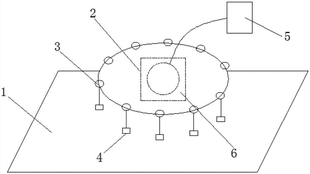
[0013] Such as figure 1 A kind of automatic control rotary workbench shown, comprises work support 2 and work surface 1, and described work support 2 is fixedly arranged on the work surface 1, and described work support 2 is internally provided with and its motor 6, and described motor 6 drives The working support 2 rotates, the motor 6 is connected with the controller 5, and the motor 6 is electrically connected with the controller 5; the working support 2 is provided with a suspension hook 3, and the suspension hook 3 is fixedly provided with a hoisting piece 4 .

[0014] The above descriptions are only preferred embodiments of the present invention, and are not intended to limit the...


PUM


Abstract

The present invention provides an automatic rotary workbench which comprises a work trestle and a work surface. The work trestle is fixedly arranged on the work surface, and inside provided with a motor which drives the work trestle to rotate. The motor is connected with a controller electrically; and the work trestle is provided with hooks whereon lifting parts are fixedly arranged. The workbench adjusts the rotational speed and direction of the motor via the controller, and further adjusts the rotational speed and direction of the work trestle to meet actual demands.

Description

technical field [0001] The invention belongs to the field of workbenches, in particular to an automatic control rotary workbench. Background technique [0002] In the assembly line operation, the linear assembly line is usually long, and the working area is relatively large; and the speed of the workbench cannot be adjusted according to actual needs. Contents of the invention [0003] In view of this, the present invention aims to propose an automatic control rotary workbench to make full use of the workspace and realize automatic control of the workbench. [0004] In order to achieve the above object, technical solution of the present invention is achieved in that way: [0005] An automatic control rotary workbench, comprising a work support and a work table surface, the work support is fixedly arranged on the work table surface, the inside of the work support is provided with a motor thereof, the motor drives the work support to rotate, and the motor is connected to a c...

Claims


Application Information

Patent Timeline
Patent Type & Authority Applications(China)
IPC IPC(8): B25H1/02B25H1/10
CPCB25H1/02B25H1/10
Inventor 马兰
Owner TIANJIN XINYUAN HONGDA TECH CO LTD
Learn More