
Rack structure of digital printing machine

A technology of digital printing machine and frame structure, which is applied to printing machines, rotary printing machines, printing, etc., which can solve problems such as burns, digital printing machine residual temperature burns, unfavorable heat dissipation, etc., to avoid burns, heat insulation, and hot pressing uniform effect

Inactive Publication Date: 2017-07-04
HAINING KUCAI DIGITAL TECH CO LTD
View PDF10 Cites 0 Cited by
  • Summary
  • Abstract
  • Description
  • Claims
  • Application Information

AI Technical Summary

Problems solved by technology

[0002] The digital printing machine can print digital patterns in a large format, and is widely used in clothing processing, drawing and other fields; the digital printing machine prints photos on the fabric by hot pressing, and due to the high temperature of the hot pressing, it is difficult to operate If you accidentally touch the heat conduction plate, it is easy to be scalded, and the high temperature and self-heating of the digital printing machine during use will lead to a higher temperature at the bottom of the digital printing machine. The bottom of the digital printing machine in the prior art is directly attached to the table. , is not conducive to heat dissipation; the digital printing machine cannot be removed immediately after the operation, and it is easy to be scalded by the residual temperature of the digital printing machine

Method used


Image

  • Rack structure of digital printing machine

Examples


Embodiment Construction

[0028] Preferred embodiments of the present invention will be described in detail below in conjunction with the accompanying drawings.

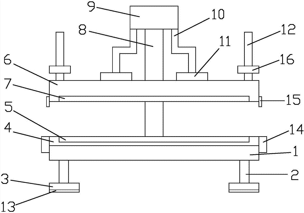
[0029] Please see attached figure 1 As shown, the present invention provides a frame structure of a digital printing machine, including a printing console 1, a plurality of bottom poles 2, a plurality of bases 3, a heat insulation protection plate 4, a heat conducting plate 5, a printing plate 6, and a pressing plate 7 , support column 8, hydraulic telescopic cylinder 9, a pair of hydraulic telescopic columns 10, a pair of connecting plates 11 and a pair of handles 12; the plurality of bottom poles 2 are vertically connected to the printing console 1 At the corners of the lower end, the plurality of bases 3 are respectively horizontally connected to the lower ends of the plurality of bottom poles 2, so that there is a gap at the bottom of the printing console 1; the heat insulation protection board 4 is arranged on the upper end surface of t...


PUM


Abstract

The invention provides a rack structure of a digital printing machine. The structure comprises a printing operating console, a plurality of bottom fulcrum bars, a plurality of bases, a heat insulating protective plate, a heat-conducting plate, a printing plate, a pressing plate, a supporting stand column, a hydraulic telescoping cylinder, a pair of hydraulic telescoping columns, a pair of connecting plates, and a pair of lifting yokes. The plurality of bottom fulcrum bars are connected with the printing operating console and the bases. The heat insulating protective plate is arranged on the upper end face of the printing operating console. The heat-conducting plate is embedded in a concave surface of the heat insulating protective plate in an adaptive manner. The pressing plate is embedded in a concave surface of the printing plate in an adaptive manner. The lower end of the supporting stand column is fixedly connected with the middle part of the rear end of the printing operating console. The hydraulic telescoping cylinder is arranged on the upper end of the supporting stand column. The hydraulic telescoping columns are connected with the hydraulic telescoping cylinder. The hydraulic telescoping column is connected with the printing plate through the connecting plate. The pair of connecting plates are respectively symmetrically arranged on two sides of the middle part of the printing plate. The pair of lifting yokes are respectively symmetrically arranged on two side edges of the printing plate. The rack structure of a digital printing machine is used for digital printing, and is uniform in hot pressing, and meanwhile heat can be effectively isolated, preventing a user from being scalded.

Description

technical field [0001] The invention relates to a digital printing machine, in particular to a frame structure of the digital printing machine. Background technique [0002] The digital printing machine can print digital patterns in a large format, and is widely used in clothing processing, drawing and other fields; the digital printing machine prints photos on the fabric by hot pressing, and due to the high temperature of the hot pressing, it is difficult to operate If you accidentally touch the heat conduction plate, it is easy to be scalded, and the high temperature and self-heating of the digital printing machine during use will lead to a higher temperature at the bottom of the digital printing machine. The bottom of the digital printing machine in the prior art is directly attached to the table. , which is not conducive to heat dissipation; the digital printing machine cannot be removed immediately after the operation is completed, and it is easy to be scalded by the re...

Claims


Application Information

Patent Timeline
Patent Type & Authority Applications(China)
IPC IPC(8): B41F17/38
CPCB41F17/38
Inventor 王继钢
Owner HAINING KUCAI DIGITAL TECH CO LTD
Learn More