
Longitudinal drum-type auxiliary propulsion device of ship

A drum-type, marine technology, applied in the direction of ship propulsion, ship parts, propulsion parts, etc., can solve the problem of large turning radius of ships, and achieve the effect of simple structure design, good turning performance and convenient installation

Inactive Publication Date: 2017-07-04
HARBIN ENG UNIV
View PDF5 Cites 5 Cited by
  • Summary
  • Abstract
  • Description
  • Claims
  • Application Information

AI Technical Summary

Problems solved by technology

Since this kind of rudder is an integral structure, the turning radius of the ship with this kind of rudder is relatively large.

Method used


Image

  • Longitudinal drum-type auxiliary propulsion device of ship
  • Longitudinal drum-type auxiliary propulsion device of ship
  • Longitudinal drum-type auxiliary propulsion device of ship

Examples


Embodiment Construction

[0014] The present invention will be further described in detail below in conjunction with the accompanying drawings and specific embodiments.

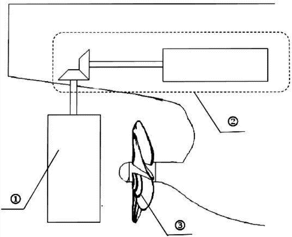
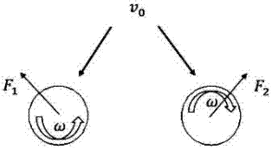
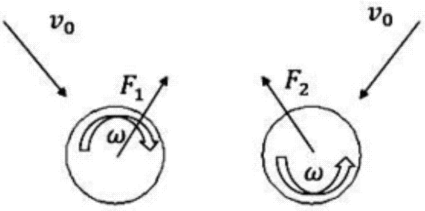
[0015] The purpose of the present invention is to reclaim the energy in the ship's wake to provide additional thrust for the ship's navigation; Figure 1 to Figure 3 , the present invention includes a pair of cylindrical drum structures 1 and a set of related driving devices 2 . The drum structure 1 is a cylindrical shell structure that can freely rotate around its respective rotation axis, its length does not exceed the draft of the ship and is completely submerged in water, and its diameter is 0.5-0.8 times the diameter of the propeller 3 . In the drum structure 1, for a single-screw boat, the two drums are located behind the propeller and deflect to the outside, and for a double-screw boat, the two drums are located behind the propeller and deflected to the inside. The drums in both cases are suspended and connected to the drive b...


PUM


Abstract

The present invention provides a longitudinal drum-type auxiliary propulsion device of a ship. Two drum-type structures are arranged at the lower end of the tail of the ship, each drum-type structure is a barrel thin-shell structure having a cylindrical shape, the upper ends of the drum-type structures are connected with a device positioned in the stern of the ship through rotatory shafts, the two drum-type structures are positioned behind ship tail propellers and provided on the same cross section of the ship, wherein the length direction of the ship is the direction of the longitudinal section, and the cross section is the plane perpendicular to the longitudinal section. According to the invention, the energy in the wake flow of the ship can be effectively absorbed, the maneuverability and the course change performance of the ship are better, the structure design is simple, installation is convenient, and certain economic requirements are met.

Description

technical field [0001] The invention relates to a longitudinal drum type ship auxiliary propulsion device, which belongs to the technical field of ship propulsion devices. Background technique [0002] The basic principle of the Magnus effect is similar to that of an airfoil generating lift. When the rotating cylinder is subjected to the flow of transverse fluid, the velocity distribution of the fluid around the cylinder will be changed. The upper half of the cylinder rotates in the direction of transverse fluid flow, increasing the velocity of the fluid. The upper half of the cylinder rotates against the direction of transverse fluid flow, reducing the velocity of the fluid. According to Bernoulli's theorem, the pressure in the upper half of the rotating cylinder is greater than the pressure in the lower half, which produces a reasonable downward P, which is called the Magnus effect force. [0003] At present, the energy-saving attachment devices used to recover the ener...

Claims


Application Information

Patent Timeline
IPC IPC(8): B63H1/00B63H25/40
CPCB63H1/00B63H25/40B63H2001/005
Inventor 赵庆新郭春雨郭航王一帆
Owner HARBIN ENG UNIV
Learn More